Adder
Designing and Simulating a Half-Adder
One of the fundamental circuits that are used in adders is half-adder. A half-adder consists of two one-bit inputs (as shown in Figure 1) A and B. It does not include any carry as input. The output of the circuit consists of two one-bit ports, C and S. The former represents the carry that might be generated while calculating the addition, and the latter is the sum of the two inputs. In total "C S" in total show the addition result of A and B. The truth table of a half-adder is shown in Table 1.
Table 1: Truth table of a half-adder
| Inputs | Outputs | ||
|---|---|---|---|
| A | B | C | S |
| 0 | 0 | 0 | 0 |
| 0 | 1 | 0 | 1 |
| 1 | 0 | 0 | 1 |
| 1 | 1 | 1 | 0 |

Figure 1: Half-adder
Tasks
- Download the SystemC code for the half-adder: half_adder.h and half_adder.cpp. The test-bench for the design is provided in half_adder_tb.cpp.
- Make sure the design of the half-adder is correct and corresponds to the truth table in Table 1.
- Compile your code with the following comamnd (you might need to change the path to your library):
g++ -I. -I$SYSTEMC_HOME/include -L. -L$SYSTEMC_HOME/lib-linux64 -Wl,-rpath=$SYSTEMC_HOME/lib-linux64 -o half_adder half_adder_tb.cpp -lsystemc -lm - Run your executable (which should be existing in the same folder with name half_adder) to genrate your VCD file.
- If everything works ok, you should be able to see a waveform such as Figure 2. For this purpose, you can use GTKWave.

Figure 2. Waveforms for simulation of a half-adder in GTKWave
- Now try to modify the test-bench so that in addition to generating waveforms on the output VCD file, it also shows the results on the console output (terminal) in text format.
Designing and Simulating a Full-Adder
The next circuit we explain in SystemC in this tutorial is a full adder. A full adder as 3 inputs, A, B and C_in (carry in) and it calculates the addition of the inputs and generates the outputs in form of S (Sum) and C_cout (Carry out). The circuit of a Full adder is shown in Figure 2, along with its truth table in Table 2.
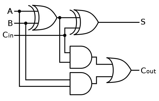
Figure 2. Full-adder
Table 2. Truth table for a half-adder
| A | B | Cin | S | Cout |
| 0 | 0 | 0 | 0 | 0 |
| 1 | 0 | 0 | 1 | 0 |
| 0 | 1 | 0 | 1 | 0 |
| 1 | 1 | 0 | 0 | 1 |
| 0 | 0 | 1 | 1 | 0 |
| 1 | 0 | 1 | 0 | 1 |
| 0 | 1 | 1 | 0 | 1 |
| 1 | 1 | 1 | 1 | 1 |
Tasks
- Download the SystemC code for the full-adder: full_adder.h and full_adder.cpp. The test-bench for the design is provided in full_adder_tb.cpp.
- Make sure the design of the full_adder is correct and corresponds to the truth table in Table 2.
- Compile your code with the following comamnd (you might need to change the path to your library):
g++ -I. -I$SYSTEMC_HOME/include -L. -L$SYSTEMC_HOME/lib-linux64 -Wl,-rpath=$SYSTEMC_HOME/lib-linux64 -o full_adder full_adder_tb.cpp -lsystemc -lm - Run your executable (which should be existing in the same folder with name full_adder) to genrate your VCD file.
- If everything works ok, you should be able to see a waveform such as Figure 3. For this purpose, you can use GTKWave.

Figure 3. Waveforms for simulation of a full-adder in GTKWave - Try to use the knowledge of creating hierarchical designs in SystemC and create a full-adder by using two half-adders (structural design). In order to make it easier, the base code is given here: full_adder_hier.h and full_adder_hier.cpp.However, you should make sure the modules are connected properly using signals. Try to make full-adder design correspond to Figure 3. Write the test-bench for the design (which should be similar to the previous full adder design. Compile the design again similar to before and verify its correctness by visualizing the outputs using waveform in GTKWave.
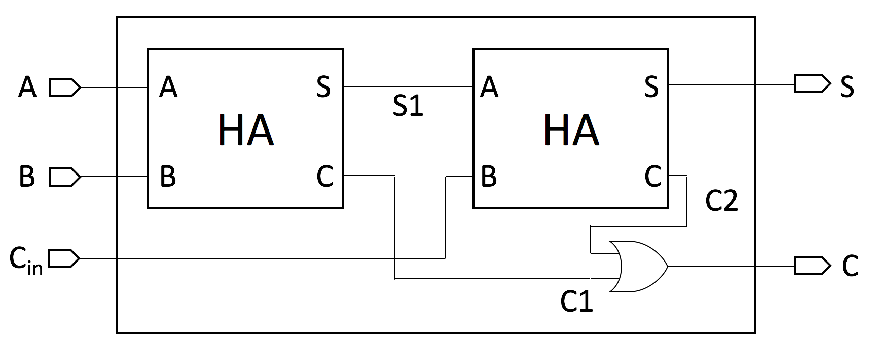
Figure 3. Structural design of a full-adder (using two half-adders)
Designing and Simulating a 4-bit Adder
In this part of the tutorial, you should already know how to make a hierarchical structural design in SystemC. Now the goal is design to make a 4-bit Ripple Carry Adder (RCA) which is implemented using full-adder modules. A 4-bit RCA based on full-adders looks like what is shown in Figure 4. This is an adder which adds two 4-bit numbers as inputs,A and B, and also accepts an input carry (Cin). On the output it generates a 4-bit Sum value along with an output carry ,if the addition results in an output carry (Cout).
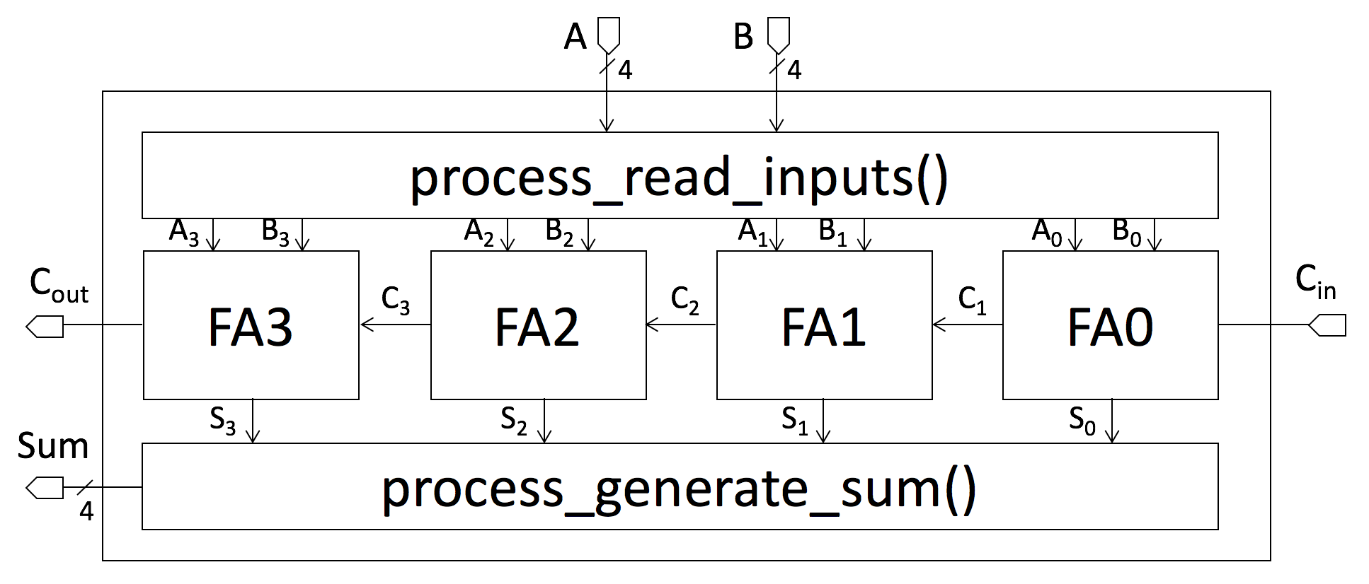
Figure 4. Structural design of a 4-bit Ripple Carry Adder (RCA) (using 4 full-adders)
Tasks
- The behavioral description code of the 4-bit adder is provided in four_bit_adder_beh.h and four_bit_adder_beh.cpp. The test-bench for the design is provided in four_bit_adder_tb.cpp.
- Try to understand the code. Now based on the knowledge from the previous tasks, redesign the 4-bit adder, according to Figure 3 (structural design). Name your files four_bit_adder_struct.h and four_bit_adder_struct.cpp.
Hint: You can use the design of the full-adder you verified in the previous task for creating the 4-bit Ripple Carry Adder (RCA). - Use the same test-bench you used for the behvarioural 4-bit adder (four_bit_adder_tb.cpp). Compile your code with the following comamnd (you might need to change the path to your library):
g++ -I. -I$SYSTEMC_HOME/include -L. -L$SYSTEMC_HOME/lib-linux64 -Wl,-rpath=$SYSTEMC_HOME/lib-linux64 -o four_bit_adder_struct four_bit_adder_tb.cpp -lsystemc -lm - Run your executable to genrate your VCD file.
- If everything works ok, you should be able to see a waveform such as Figure 5. For this purpose, you can use GTKWave.
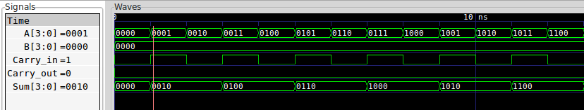
Figure 5. Waveforms for simulation of a 4-bit Ripple Carre Adder (RCA) in GTKWave
Questions
- What is the disadvantage of a Ripple Carry Adder (RCA) ? Do you know any alternative(s) ?
- Imagine your design has an input port of type sc_uint<4>. Can you read the values this port bit by bit to binary signals?
If your answer is no, how would you solve this ?
Related Readings