Decoder and Encoder
Task description
In this tutorial we focus on two other combinational circuits that are used in many complex circuits.
Decoder
Decoders have usually N inputs and a maximum of 2N outputs. For example, samples of decoders can be 1 to 2, 2 to 4 and 3 to 8 decoder. Table 1 shows the truth table for a 2 to 4 decoder. As it can be seen each combination of input bits (A and B) generate a unique output (D0, D1, D2, D3), which is a maximum of 4 different combinations. In each line of the truth table, only one output bit with the value of “logic one” can be found. As a summary, in a decoder, a binary number comes as input and essentially chooses which wire on the output to send a signal with the value “one” on it. A decoder can also have an enable input, such as the one shown in Figure 1. Whenever enable=0, all outputs would be zero and whenever enable=1, the decoder works normally. One usage of decoder is in decoding addresses for memory access.
Table 1. Truth table for a 2 to 4 decoder
| A | B | D0 | D1 | D2 | D3 |
| 0 | 0 | 1 | 0 | 0 | 0 |
| 0 | 1 | 0 | 1 | 0 | 0 |
| 1 | 0 | 0 | 0 | 1 | 0 |
| 1 | 1 | 0 | 0 | 0 | 1 |
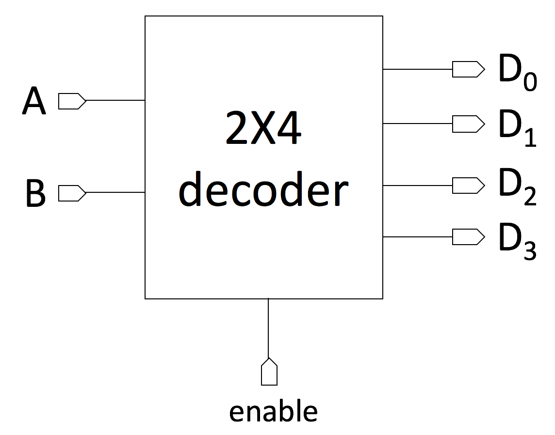
Figure 1. A 2 to 4 decoder with enable input
Tasks
- In this tutorial, first we will start with the design of a 2 to 4 decoder with enable. Please study the logic of the decoder and how it works by reading the decoder.h and decoder.cpp files. Also, the test-bench for the 2 to 4 decoder is provided in decoder_tb.cpp. Make sure the logic of the decoder is written correctly.
- Compile your code with the following command (you might need to change the path to your library):
g++ -I. -I$SYSTEMC_HOME/include -L. -L$SYSTEMC_HOME/lib-linux64 -Wl,-rpath=$SYSTEMC_HOME/lib-linux64 -o decoder decoder_tb.cpp -lsystemc -lm . - If everything is done correctly, the generated VCD file should also generate a waveform like the one shown in Figure 2 in GTKWave.
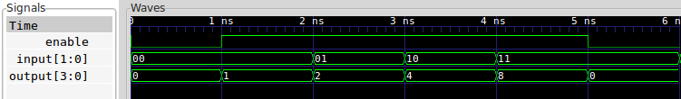
Figure 2. Waveforms for a 2 to 4 decoder in GTKWave
- Try to use the concept of hierarchical design and design a 3 to 8 decoder using structural design.
Hint: In order to create a 3 to 8 decoder, you can use 2 to 4 decoders and with a small logic. Try to figure out how many 2 to 4 decoders you need to design a 3 to 8 decoder. - Create your design and also write a test-bench for the 3 to 8 decoder. Try to use the the test-bench for the 2 to 4 decoder decoder_tb.cpp as template. Verify your design and visualize the signals using GTKWave. Make sure the decoder is working correcting and each input combination generates exactly only one active output (a unique output).
- Considering the knowledge you already have about how a full-adder and a decoder work, try to design a full adder using a 3 to 8 decoder.
Hint: It might not be necessary to use all the outputs of the decoder. The goal is to create the Sum and Carry_out signals as the outputs of the full-adder, by using a decoder. The inputs A, B and C_in of the full-adder should be connected to the 3 inputs of the 3 to 8 decoder.
Encoder
Encoders work in the opposite way as decoders. That means an encoder with a maximum of 2N inputs, can generate N outputs. On the inputs, only one bit at each time can be set to one, making each input value unique. Each of these unique inputs generates a binary number on the output which is the encoded value of the input. In other words, when a bit comes in on an input wire, the encoder outputs the physical address of that wire. Similar to a decoder, an encoder can also have an enable input, which whenever is set to one, the encoder works normally. A sample 4 to 2 encoder with enable input is shown in Figure 3.
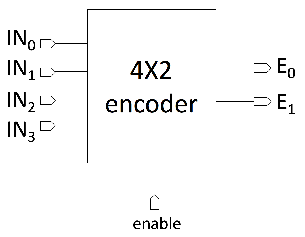
Figure 3. A 4 to 2 encoder with enable input
Tasks
- Please study the logic of the 4 to 2 encoder and how it works by reading the encoder.h and encoder.cpp files. Also, the test-bench for the 4 to 2 encoder is provided in encoder_tb.cpp.
- Make sure the logic of the encoder is written correctly.
- Compile your code with the following command (you might need to change the path to your library):
g++ -I. -I$SYSTEMC_HOME/include -L. -L$SYSTEMC_HOME/lib-linux64 -Wl,-rpath=$SYSTEMC_HOME/lib-linux64 -o encoder encoder_tb.cpp -lsystemc -lm . - If everything is done correctly, the generated VCD file should also generate a waveform like the one shown in Figure 4 in GTKWave.

Figure 4. Waveforms for a 4 to 2 encoder in GTKWave - Try to use the concept of hierarchical design and design a 8 to 3 encoder using structural design. Try to figure out how many 4 to 2 encoder you need to design a 8 to 3 encoder. Hint: Similar to the decoder, in order to create a 8 to 3 encoder, you can use 4 to 2 encoders and with a small logic.
- Write a test-bench for the 8 to 3 encoder. Try to use the the test-bench for the 4 to 2 encoder encoder_tb.cpp as the template. Verify your design and visualize the signals on GTKWave. Make sure the encoder is working correcting and each input combination generates exactly one unique binary value on the output.
Related Readings