In this lab you will be learn how to model Encoder and a decoder.
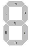
Table 1: Decoder values
| Input values |
7-segment output |
| 0000 |
0 |
| 0001 |
1 |
| 0010 |
2 |
| 0100 |
3 |
| 1000 |
4 |
| any other value |
F |
Tasks
- Design a Decoder that can take inputs from Switches and show the outputs of this design on Seven Segment as shown in table above. You can take insparation from seven segment decoder in excercise 2.
- Make a VHDL file with following inputs and outputs
Table 2
Table 2: Decoder Input/Outputs
| I/O | Signal Name | Diminution | Type |
| Input | Switches | 3 downto 0 | std_logic_vector |
| Output | AN | 3 downto 0 | std_logic_vector |
| Output | Seven_Segment | 6 downto 0 | std_logic_vector |
- Make a case statement inspired within a process inspired by Excercise 2 counter.vhd which behaves according to table 1.
- Write a Testbench which tests all possible combinations of inputs and simulate it in modelsim and verify the behaviour
- Make a UCF file and synthesize the design synthesize and validate if the design works.
- Now you will Display FISH on the four seven segment displays of your FPGA.
- Read the manual for the FPGA that you have and see how the seven segment works. Specially focus on how to show different values on your Seven segments.
- Design the two decoders (fish_select,AN_select)in separate entities. As shown in Figure below
 The AN translates to AN0, AN1, AN2; An3, and Seven_segment translates to CA, CB,CC,CD,CF,CG

- Design a counter inspired from the lab1 counter using numaric_std library.
- Design a top level to connect them all together
- Write a testbench to test your design. Simulate the design and verify if you can see the values switching
- Make a UCF and validate if the design works
Related Readings