Finite State Machine: Elevator
Now we will make a finite state machine for an elevator. At the end of this lab, you will run your program on a model lift, which we built for testing your designs (see figure below).
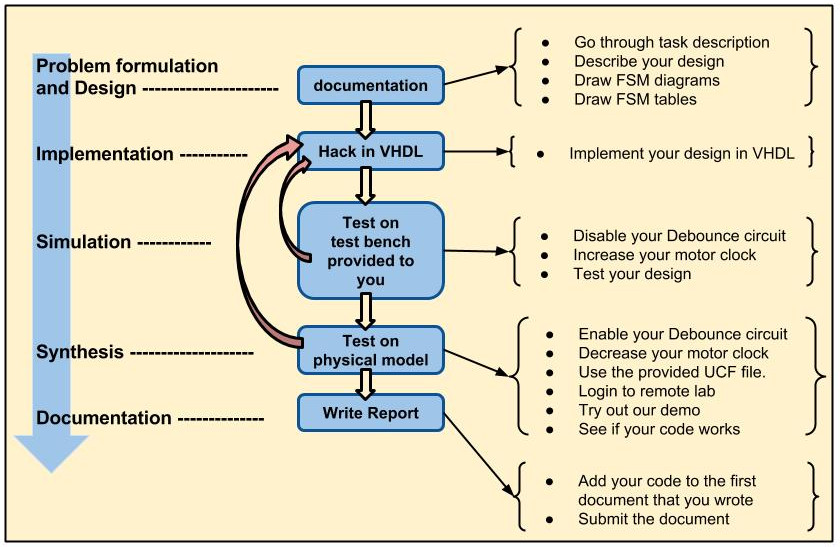
- This is an open task which means that there can be many correct designs. So you must come up with a good motivation
for each supposition you made. Do not forget to write these suppositions and the motivations in your report. Therefore we start with the report.
- Written Documentation:Since this task requires a lot of design decisions it is important that the students maintain a strong documentation.
Therefore based on the specifications given below, design the Finite State Machines on paper. make the transition tables. Decide on mealy and Moore approaches.
Any extra hardware which might be needed by the Finite State Machines can be used added separately and may work as an input to the state machine
- Refine the Figure 5 based on your design decisions. Motivate each decision with a rational reasoning. Template for the Report can be found here.
- Top level design entity which is given in the table 4.
Table 4: Top Entity Ports
| Name | Port | type |
| clk | in | STD_LOGIC |
| sensors | in | STD_LOGIC_VECTOR (4 DOWNTO 0) |
| calls | in | STD_LOGIC_VECTOR (4 DOWNTO 0) |
| menu | in | STD_LOGIC_VECTOR (4 DOWNTO 0) |
| motor | out | STD_LOGIC_VECTOR (1 DOWNTO 0) |
| sleep | out | STD_LOGIC |
| ss | out | STD_LOGIC_VECTOR (6 DOWNTO 0) |
- Now we should understand all the components within the design. These components are shown in figure 5.
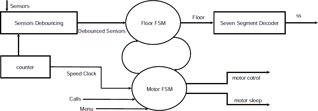
Fig.5:: System Components
- Counter is a 24 bit counter in the design.
- Sensors should be designed according to the following functionality
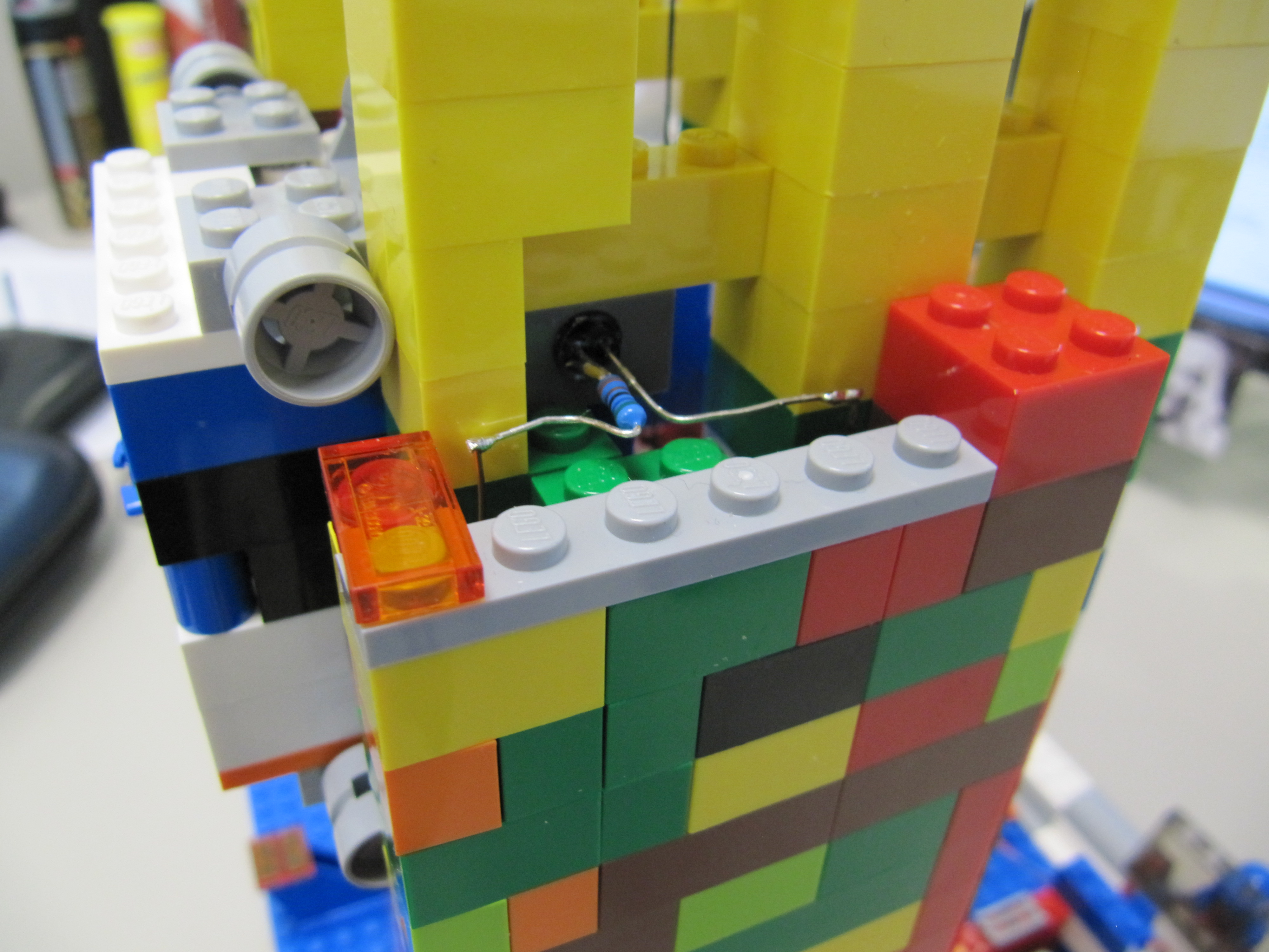
Fig.6:: Infra red sensors in the Model
- Sensors are prone to bouncing because of vibrations in the lift which might not be visible to the naked eye but is visible to the sensors.
Hence the sensors need to be de-bounced by a three bit shift register with 19th bit of counter slowing the de-bouncing circuit.
- The lift has five ray cut Infra-Red (IR) sensors.
- When ever a sensors ray is cut by the lift it sends a signal '1' to the FPGA. Otherwise the sensor sends a '0'
- Each sensor is placed between floors and there can be blind spots between each sensor. When the lift is in a blind spot all sensors send "00000" to the FPGA.
This is the time when the lift is moving between two sensors. At this point sensors can also recieve value from two sensors as well.
(e.g. on the second floor sensors can either have a value "00000" or "00110".) It is recommended that both cases should be handled by the designer.
(hint: rather then looking for sensor ="00100" look for sensor(2)= "1".)
- Seven segment should work as follows
- Seven segment decoder decodes the current floor into seven segment output.
- keep in mind that unlike seven segments on Nexys FPGAs you do not need to specify the anode.
- Each segment is turned on by logic value 1. Seven segment should also be able to blink 5 times after it reaches a floor.
- Unlike nexys 2/3 board's seven segment the pin orientation is opposite. (i-e. seven segment <= "abcdefg";)
- When the elevator reach a particular floor then it should stop and blink the floor number for 5 seconds.
- Motor should be controlled in the following manner by motor FSM

Fig.7:: Stepper motor in the model
- Motor FSM generates motor. It generates three signals.
- Motor(0) controls the direction of the motor. Where '1' is DOWN '0' is up
- Motor(1) generates a clock signal which controls the speed of the motor. The speed is specified by a clk like signal by changing its frequency.
The recommended speed of Motor can be given by sending 10th bit of the counter.
- A sleep signal turns off the motor. In idle state the motor should be kept turned off. where '1' is ON and '0' is OFF
- Motor FSM should also shares its Status with Floor FSM ( i.e. idle, going up, going down, blinking Seven segment)
- The Floor FSM should work in the following manner.
- FSM floor calculates the current floor based on the sensor and the Motor FSM status (direction sleep).
- The sensors have blind spots Hence the floor FSM should remember its own floor while passing through the blind spot
Write each component and test component them separately.
Once each block is verified according to the specifications then instantiation them together and test it.
Test the complete design against the given VHDL Test Bench
Once all the test pass, write a test bench in verilog to test the design. You may require a wrapper to integrate the VHDL design within Verilog.
Download the UCF File and implement the design on the Xula FPGA (xs3s200a-4vq100) .You will be using XULA boards to do so. Read Xula reference manual.
To test the behavior of the lift and play with it, we have provided you a working demo that you can use to program FPGA.(to use the model you should be inside the ATI network, meaning that you have to be sitting in a lab!)
NOTE: This model has 5 floors, the 5th floor is not accessible since there is a hardware break to prevent bad designs to break through the roof.
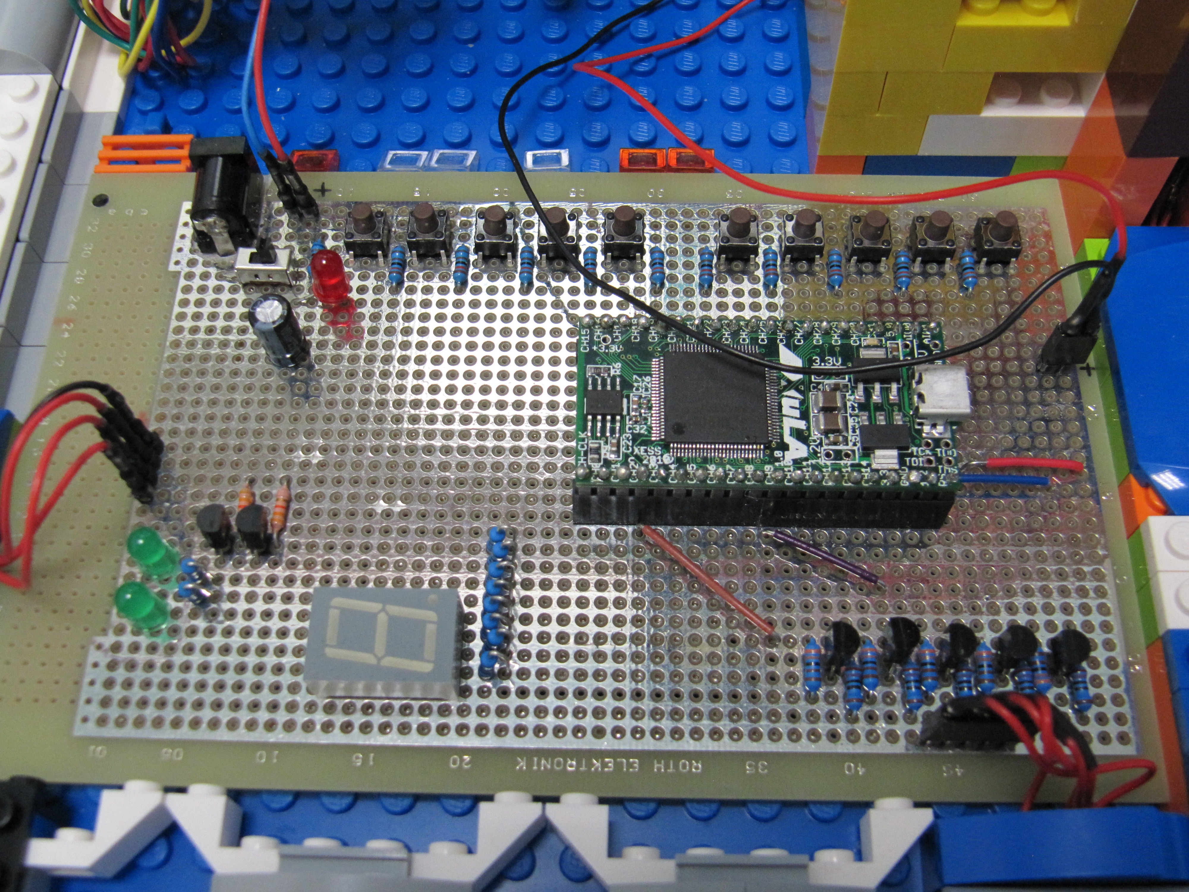
Fig.8:: Xula and prototype board
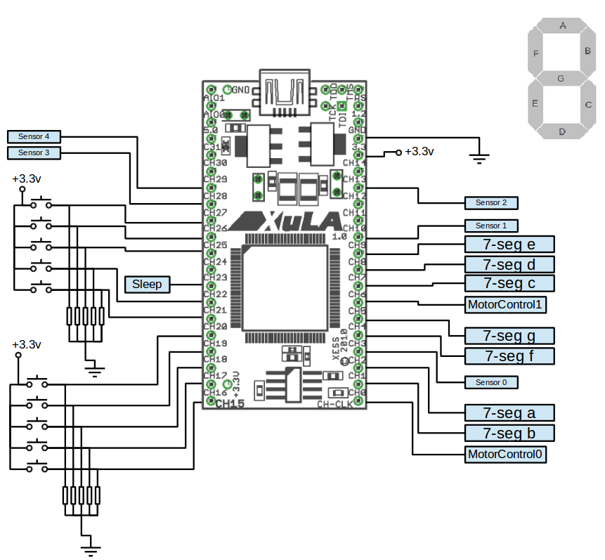
Fig.9:: schematic of prototype board

Related Readings