Finite State Machines
Introduction to FSM
- Consider the following state machine shown in Figure 1. This is a meelay state machine takes one input and looks for a pattern 0110. When ever the pattern is found it gives an output 1.
- Make a table next state logic table
- Similarly, make a table output logic table.
- Design a VHDL entity with Inputs and outputs as shown in Table 3, as shown in figure below:
- Design an architecture with following three process blocks
- next state logic decoder based on table 1
- two bit state register to store states from s0 to s3
- output logic decoder based on table 2
- write a test bench which provides a test pattern of 0,1,1,0,1,1,0,0,1,1,0,1,1,1,1,1
- Draw a Moore state Machine for the same purpose as shown in the figure below. and describe how it may differ from the current design.
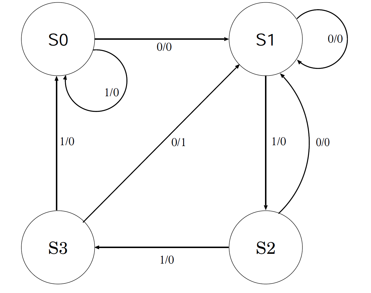 Fig.1: Example Finite State Machine
| Name | Port | type |
| clk | in | STD_LOGIC |
| inp | in | STD_LOGIC |
| outp | out | STD_LOGIC |
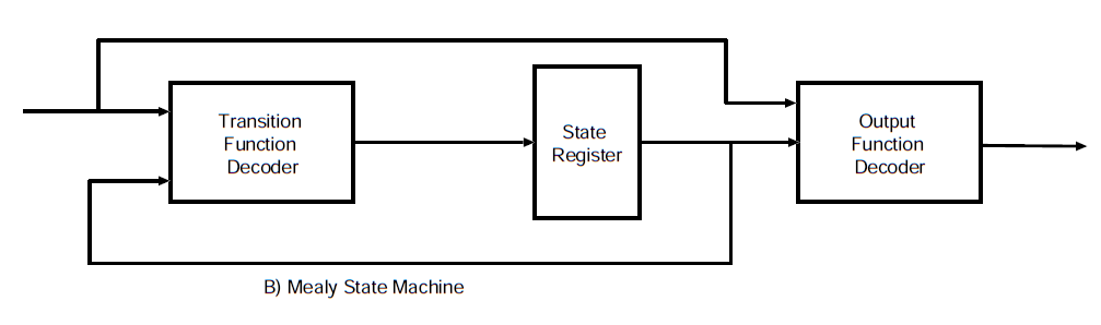 Fig.2:: Mealy machine
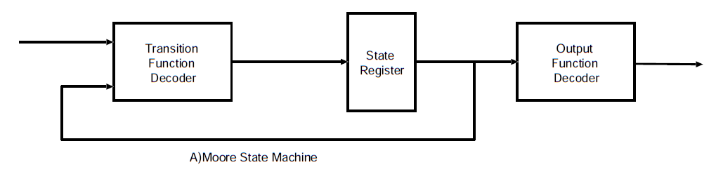 Fig.3:: Moore machine
Related Readings