Packages and Busses
Introduction
In this lab you will learn how to make your own package, How function and operations are resolved and you will also learn to design a bus in vhdl. You are recommended to use modelsim to perform the following operations.Tasks
- Open ModelSim and open the 1164 standard library. Library → IEEE → std_logic_vector → right click → edit (But do not Edit it)
- This package defines the standard representation of std_logic/std_logic vector e.g. the possible values of a standard logic (multi-valued logic) and how it is resolved. The representation of logic is given by following code.
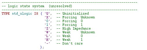
Here std_ulogic is defines a Type based on all possible values.

Here std_logic is defined as a subtype of std_ulogic which uses a resolution function called resolve.
The resolution function resolves conflict within multiple levels of which drive a particularly std_logic. To do so they require a resolution table.

This resolution table is used within the body of the resolved function to resolve these conflicts.

- Make a package for your own multi valued logic.
In the IEEE library you can find the definitions for the IEEE standard 1164 which uses nine-valued-logic.
Use those as a template and define your own enumerated data type ttu that can handle open collector logic with the following interpretation:
- 'X', -- Forcing Unknown,
- '0', -- Forcing 0,
- '1', -- Forcing 1,
- 'Z', -- High Impedance,
- 'H', -- Weak 1,
- Make a resolution function similar to the resolution function given in the IEEE std_logic_1164 package.
- Use a table lookup for the evaluation of any two pairs of ttu. No if- or case statements are allowed.
Remember that a normal open collector resolution function assumes that the driving strengths of the zero is much stronger than the driving strength of the one.
Define new types ttu_logic and ttu_logic_vector that use your ttu resolution function.
- What is the interpretation of the table lookup?
- Now we want to test that the open collector function work properly.
You can try to go through all possible combinations.
To do this with a multi-valued signal is a bit trickier.
First, we have to loop through all values in the new type,
and then we have to make sure that the other signal is updated at an interval that is long enough for the first one to go through all values.
To do this, we use the test pattern generator which incorporates following logic.

- Why is the clock period of clk2 50 ns when the clock period of clk1 is 10 ns?
- In which order are the values selected from ttu by the FOR - LOOP statement? Why that particular order?
- Now we will perform an overloading of operators
- Redefine and overload the operator XOR for the ttu type. Include the operator in your previous made package. As before, use the table lookup style of writing.
- Test your function with the same test pattern as before, although instead of assigning both values to the same wire, assign one of them to a signal a, and
the other to a signal b and use a dataflow statement to evaluate the XOR-functionality.
- Is it possible to define a new operator XNOR, which will perform the operation NOT(a XOR b) in VHDL'87? What about VHDL'93? (HINT! Try to compile with VHDL'87 and VHDL'93, respectively, by changing the default in the compiler options menu)
- Prototyping a Data bus
- The last task is to prototype a data bus onto the FPGA-board and evaluate how FPGAs interpret data buses. Write a VHDL component that connects two registers with four bits each to a data bus. Then connect the two registers to the DIP switches of the FPGA board and connect the individual bits of the data bus to four LED segments of your choice. Prototype your design and see what functionality that the resulting bus gets. A lso, examine the produced layout and see how the Xilinx ISE has connected the components on the data bus together. Use the Technology viewer (Post-mapping) and click your way down in the hierarchy and go inside the Tri-state function. The equations are shown if you place the mouse pointer on top of the LUT.
- What functionality does the data bus exhibit and how are the wires on the bus (actually) connected?
Related Readings