Exercise #11: Pico-CPU (Design and test your Pico-Controller Unit)
Important Note:
Please make sure you read Jiri Gaisler's "A structured VHDL design method". This
document would be used as our coding reference throughout the labs. Your designs would are not acceptable if you do not follow 2 process architectrue as a design rule.
Control Unit Design
Control unit of our Pico-CPU, consists of an instruction register, instruction
decoder, control logic and program counter to produce the address of the
next instruction to be executed.
Instruction Cycles
Our Pico CPU, will have the following cycles:
- Fetch: in this phase, we processor fetches an instruction (according to
program counter)from instruction memory and writes it in Instruction
Register
- Decode: fetched instruction Op-Code will be decoded and data or
address will be extracted
- Execution: data will be fed to Datapath Unit and instruction will be
executed
- Write-Back: the result of the operation will be written to Data Mem-
ory
Instruction Decoder
Instruction Decoder is a 5 to 32 bit decoder that will take Op-Code as input
and will define which instruction has been selected. A block diagram of
connections of Instruction Register to Instruction Register and Control unit
is shown in figure 1.
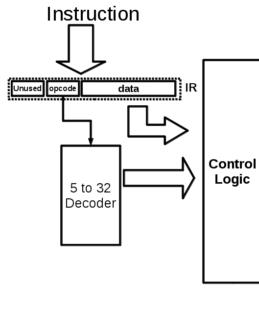
figure 1
Control logic
You will design this part of your lab by implementing an FSM to take
care of the whole process. so basically the FSM goes through different
instruction cycles, and produces the control signals accordingly. Since you
already designed your DataPath and Memory system, you should be able to
identify what are the control signals that you need in each operation, when
should you issue read/write signals to memory etc.
Testing Control Unit
Now that you have completed Control Unit design, you should test it. To
do so, your test bench should mimic the behavior of the other components
so you can fully test your design. It is very crucial specially in the case of
flags and how they affect the PC.
Questions
before you proceed to next section, you should be able to answer the following questions.
- How should Program counter count if you have an 8 bit instruction
memory word?
- How many clock cycles does it take to execute one instruction? what
is the performance of your CPU in terms of Instructions per Clock
cycles?
- Can we do better than this (in terms of performance)? if yes, then
what can we do? (considering no pipeline or fancy stuff)
Putting CPU together
In this part we need to connect all those different parts of our Pico-CPU
together and test it. To do so, we need to define a top module entity called
PicoCPU and instantiate all the modules.
To test the CPU, we can use a test setup similar to our memory test as
shown in figure 2.
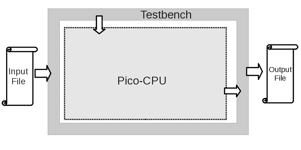
figure 1
You can hack in your instructions into this sample assmebler for generating your machine code. just follow the comments in the code. when your pico-assembler is finished just
compile it along with your assembly-like code you have written. make sure you are following the naming conventions for files (Note: this is actually a Pico assembler and cant do many things. it just translate
each line of your code into some machine code you have defined). enjoy!
epilogue
Congratulations. You finished the Pico-CPU lab. We hereby dub thee
a "Pico-CPU Designer". If you want to continue working on CPU architecture design, contact
Siavoosh.