Important Note:
Please make sure you read Jiri Gaisler's "A structured VHDL design method". This document would be used as our coding reference throughout the labs.Format of Exercises
Before coming into the exercise sessions, students are required to understand prerequisites for each session. When the students arrive in the laboratory, they can be tested for following concepts for work,- A deep understanding of required concept of labs as explained in per-Requisite sessions of each exercise manual on the course website
- Written solution of problems given in Pr-requisite section
- Softcopy of codes/scripts which students might need for the rest of the tasks
Tools user guides and manuals
You can find the user guides and manuals for these labs here:Task description
In this lab you will be learn how to model Encoder and a decoder.
| Input values | Seven segment output display |
| 0000 | 0 |
| 0001 | 1 |
| 0010 | 2 |
| 0100 | 3 |
| 1000 | 4 |
| any other value | F |
Tasks
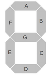
- Design a Decoder that can take inputs from Switches and show the outputs of this design on Seven Segment as shown in table above. You can take insparation from seven segment decoder in excercise 2.
- Make a VHDL file with following inputs and outputs
Table 2
Table 2: Decoder Input/Outputs I/O Signal Name Diminution Type Input Switches 3 downto 0 std_logic_vector Output AN 3 downto 0 std_logic_vector Output Seven_Segment 6 downto 0 std_logic_vector - Make a case statement inspired within a process inspired by Excercise 2 counter.vhd which behaves according to table 1.
- Write a Testbench which tests all possible combinations of inputs and simulate it in modelsim and verify the behaviour
- Make a UCF file and synthesize the design synthesize and validate if the design works.
- Make a VHDL file with following inputs and outputs
Table 2
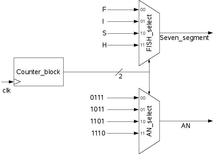
- Now you will Display FISH on the four seven segment displays of your FPGA.
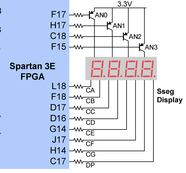
- Read the manual for the FPGA that you have and see how the seven segment works. Specially focus on how to show different values on your Seven segments.
- Design the two decoders (fish_select,AN_select)in separate entities. As shown in Figure below
 The AN translates to AN0, AN1, AN2; An3, and Seven_segment translates to CA, CB,CC,CD,CF,CG

- Design a counter inspired from the lab1 counter using numaric_std library.
- Design a top level to connect them all together
- Write a testbench to test your design. Simulate the design and verify if you can see the values switching
- Make a UCF and validate if the design works