Exercise #9: Pico-CPU (Design and test your Pico-DPU)
In this lab we design a simple 8-bit CPU. to go through the lab easily, we
have divided your tasks into three different parts, introductory materials,
preparation before entering the lab and the tasks that you have to perform
during the lab.
Important: You MUST go through the preliminary readings before you start your lab.
Important: You MUST finish lab preparation before entering the lab for Pico-CPU.
Important: You MUST bring instruction table which you make during preparation,
to lab on every session. (for labs 9,10 and 11)
Important Note: Please make sure you read Jiri Gaisler's "A structured VHDL design method". This
document would be used as our coding reference throughout the labs. Your designs would are not acceptable if you do not follow 2 process architectrue as a design rule.
Design your Pico-DPU
According to our Instruction Set, our Pico-CPU should be able to perform
the following operations:
- Add/Subtract
- Increment/Decrement
- Arithmetic and Logical Shift and Rotate through Carry Flag
- Logical operations: AND, OR, XOR, NOT
- Set/Clearing AC register and Flags
DPU Flags and Comparator
We would like to have the following flags in our ALU:
- Z: Zero Flag, will be set to 1 if the result in AC is equal to 0.
- OV: Overflow Flag will be set to one if the result of an operation is
bigger than the maximum allowed number.
These flags will be used for jump operations in Control Unit. Some processors
keep these flags in a separate register called "Status Register", which is
accessible to the programmer, but for our processor, we will keep them only
accessible through jump operations.
To implement Zero flag we need to be sure that whether all the bits are zero
or not, we can just directly use logical AND of negative of all the accumulator
register bits together (equivalent to NOR) and produce our zero signal
as shown in figure 1.
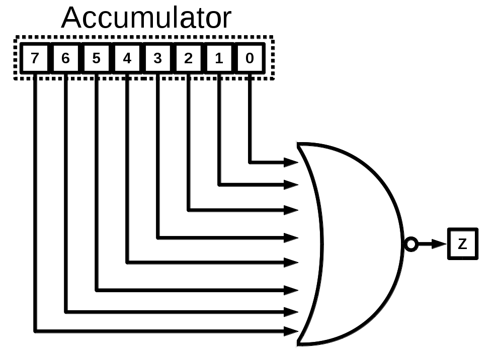
figure 1
Over flow happens when we are handling signed values and the result of
operation is bigger than our bitwidth and this results in change in sign bit
of the result. An example of this is adding 72 + 81 which should be 153 but
since we have a signed representation, it will result in -103. An easy way
to determine OV flag is to figure out if both inputs are positive or both are
negative, then the result has the same sign. So if we are adding/subtracting
two 8-bit signed operands namely A and B, and we get result R, then we
can build our OV signal as:

figure 1
Testing your DPU
To test our DPU, we need to provide control signals for different ALU
operations along with data form control unit side and memory side. Block
diagram of the test setup is show in figure 2.
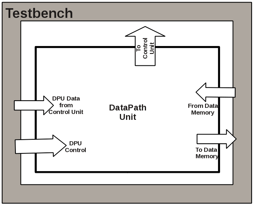
figure 2
Questions
before you proceed, you should be able to answer the following questions.
- How can you compute addition/subtraction of two 16 bit numbers using your DPU?
- Can you perform fixed point addition/subtraction with your DPU?
- Can you perform floating point addition/subtraction with your DPU?
- How can you compare two numbers with your DPU?