Difference between revisions of "FPGA Controller PC-Board"
From ATI public wiki
(→Schematics and PCB files) |
m |
||
| (2 intermediate revisions by the same user not shown) | |||
| Line 1: | Line 1: | ||
| − | |||
| − | |||
| − | |||
| − | |||
=Schematics and PCB files= | =Schematics and PCB files= | ||
| − | [[File: | + | [[File:Screen Shot 2015-05-18 at 12.44.01.png|400px|right]] |
| + | [[File:Screen Shot 2015-05-18 at 12.44.20.png|400px|right]] | ||
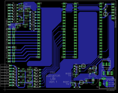
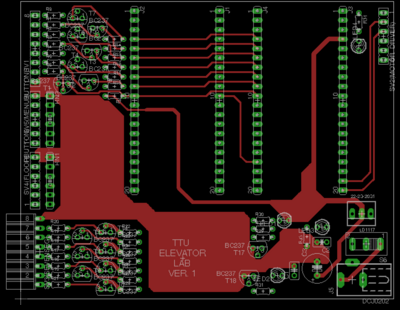
You can find the schematics and PCB files for this version in the [https://github.com/siavooshpayandehazad/TTU_ElevatorLab/tree/master/SchematicsAndPCB GIT repository for PCB files]. | You can find the schematics and PCB files for this version in the [https://github.com/siavooshpayandehazad/TTU_ElevatorLab/tree/master/SchematicsAndPCB GIT repository for PCB files]. | ||
| + | Here are some updates from the previous version: | ||
| + | * The Safety-Monitoring system can check all the sensors and monitor the behaviour of the lift more carefully. | ||
| + | * On-Board seven-segment display has been removed. Each floor has a separate seven segment. | ||
| + | * Heat-sink was added to the regulator IC | ||
Latest revision as of 09:25, 21 May 2015
Schematics and PCB files
You can find the schematics and PCB files for this version in the GIT repository for PCB files. Here are some updates from the previous version:
- The Safety-Monitoring system can check all the sensors and monitor the behaviour of the lift more carefully.
- On-Board seven-segment display has been removed. Each floor has a separate seven segment.
- Heat-sink was added to the regulator IC

