LIFT
Lift Project is one of the projects designed in department of computer engineering at TTU as a lab project. The main task in this lab is to design a controller for an elevator. Goals of this lab are:
- to undrestand Finite State Machine (FSM) design
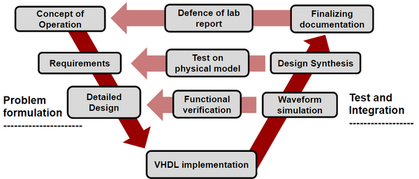
The process of this lab is described in Fig. 1. Students first have to describe the controller by providing FSM diagrams and transition tables to the staff and then go through a process of implementation, synthesis and verification. In the end they are required to submit a report.
Contents
Physical Model
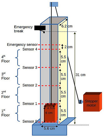
This model has 5 floors but the last floor is reserved for security reasons.The schematic of the model is shown in Fig. 2. Each floor has a sensor and on the top floor there is an emergency break that stops the cabin from going through the roof. Before reaching the emergency break, there is an emergency sensor that is connected to a safty monitoring mechanism that is responsible of preventing hardware breaks. The thread is being pulled by a stepper motor which is placed at the first floor. There are no elevator doors included in the model at the time of writing this document.
Lego structure
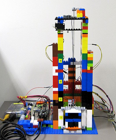
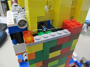
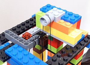
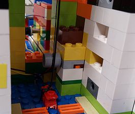
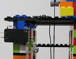
Based on the task specifications a lego model has been built for this lab. Figures 3 to 9 show different parts of the lego model.
Controller circuit
The controller circuit is equipped with an FPGA and is monitoring sensor behaviour and issueing control signals to motor driver circuit based on the calls it gets from inner and outer cabin buttons.
first prototype
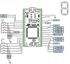
In the first verion of control board, a Xula FPGA (xs3s200a-4vq100) board has been used (XULA board reference manual). Pin configuration of this board has been shown in Fig. 10.
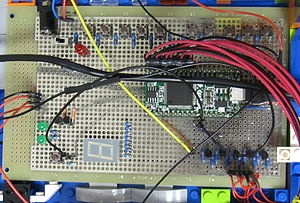
The first prototype control board provides the following functionalities (see Fig.11):
- Seven segment display
- Infra Red (IR) sensors at each floor note: we need schematic of sensor circuit here
- Inner and outer cabin push buttons
- Motor state indicator LEDs note: which LED shows what?
- Software reset button
- Hardware break at top floor
- Power switch for motor
System Components, Signal Names and Description
Top level design entity that students are required to design's interface has been described in the table below:
| Name | Port | type |
|---|---|---|
| clk | in | STD_LOGIC |
| sensors | in | STD_LOGIC_VECTOR (4 DOWNTO 0) |
| calls | in | STD_LOGIC_VECTOR (4 DOWNTO 0) |
| menu | in | STD_LOGIC_VECTOR (4 DOWNTO 0) |
| rst | in | STD_LOGIC |
| motor | out | STD_LOGIC_VECTOR (1 DOWNTO 0) |
| sleep | out | STD_LOGIC |
| Seven_Segment | out | STD_LOGIC_VECTOR (6 DOWNTO 0) |
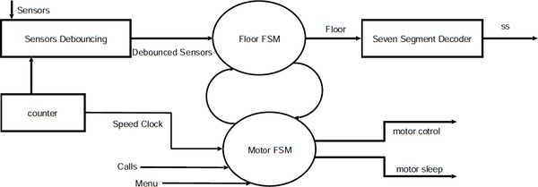
The control system itself has different components that have been shown in Fig. 12. In this figure:
- Counter is a 24 bit counter in the design.
- Sensors should be designed according to the following functionality (see Fig. 4):
- Sensors are prone to bouncing because of vibrations in the lift which might not be visible to the naked eye but is visible to the sensors. Hence the sensors need to be de-bounced by a three bit shift register with 19th bit of counter slowing the de-bouncing circuit.
- The lift has five ray cut Infra-Red (IR) sensors.
- When ever a sensors ray is cut by the lift it sends a signal '1' to the FPGA. Otherwise the sensor sends a '0'
- Each sensor is placed between floors and there can be blind spots between each sensor. When the lift is in a blind spot all sensors send "00000" to the FPGA. This is the time when the lift is moving between two sensors. At this point sensors can also recieve value from two sensors as well. (e.g. on the second floor sensors can either have a value "00000" or "00110".) It is recommended that both cases should be handled by the designer. (hint: rather then looking for sensor ="00100" look for sensor(2)= "1".)
- Motor should be controlled in the following manner by motor FSM (see Fig. 8)
- Motor(0) controls the direction of the motor. Where '1' is DOWN '0' is up
- Motor(1) generates a clock signal which controls the speed of the motor. The speed is specified by a clk like signal by changing its frequency. The recommended speed of Motor can be given by sending 10th bit of the counter.
- A sleep signal turns off the motor. In idle state the motor should be kept turned off. where '1' is ON and '0' is OFF
- Motor FSM should also shares its Status with Floor FSM ( i.e. idle, going up, going down, blinking Seven segment)
- Seven segments should work as follows
- Seven segment decoder decodes the current floor into seven segment output.
- while designing 7seg decoder you should keep in mind that unlike seven segments on Nexys FPGAs you do not need to specify the anode.
- Each segment is turned on by logic value 1. Seven segment should also be able to blink 5 times after it reaches a floor.
- Unlike nexys 2/3 board's seven segment the pin orientation is opposite. (i-e. seven segment <= "abcdefg";)
- When the elevator reach a particular floor then it should stop and blink the floor number for 5 seconds.
- The Floor FSM should work in the following manner.
- FSM floor calculates the current floor based on the sensor and the Motor FSM status (direction sleep).
- The sensors have blind spots Hence the floor FSM should remember its own floor while passing through the blind spot
The User Constraints File (UCF) File
The following code is the UCF file for XULA board:
 NET "clk" LOC = P43;
 NET "m0" LOC = P56; # Direction
 NET "m1" LOC = P13; # step clock
 NET sleep LOC = P44; # sleep to disable the motor

 NET "Seven_Segment(6)" LOC = P37;
 NET "Seven_Segment(5)" LOC = P36;
 NET "Seven_Segment(4)" LOC = P57;
 NET "Seven_Segment(3)" LOC = P61;
 NET "Seven_Segment(2)" LOC = P62;
 NET "Seven_Segment(1)" LOC = P50;
 NET "Seven_Segment(0)" LOC = P52;

 NET "calls(0)" LOC = P21;
 NET "calls(1)" LOC = P32;
 NET "calls(2)" LOC = P33;
 NET "calls(3)" LOC = P34;
 NET "calls(4)" LOC = P35;

 NET "menu(0)" LOC = P3;
 NET "menu(1)" LOC = P4;
 NET "menu(2)" LOC = P7;
 NET "menu(3)" LOC = P19;
 NET "menu(4)" LOC = P20;

 NET "sensors_in(0)" LOC = P39;
 NET "sensors_in(1)" LOC = P68;
 NET "sensors_in(2)" LOC = P82;
 NET "sensors_in(3)" LOC = P97;
 NET "sensors_in(4)" LOC = P94;
Safty Monitoring Mechanism
Since this model is designed to be controled remotely, it should be able to maintain its functionality even if it is programmed with a faulty design. For this reason we need some monitoring system to guarantee the functionality.
hardware break
A physical switch has been installed on the top floor to prevent faulty designs to go through the roof. Basically this switch is placed for worst case scenarios where there is no other way to prevent the catastrophe and where it cuts the motor power and stops the motor.
behaviour monitor
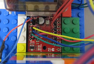
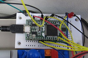
Since reaching hardware break will require human intervention and it would not always possible (in times that an operator is not present etc.), a behavior monitor system (see Fig. 13) has been added to the lift. Motor control signals goes through the monitoring system which has another Xula FPGA (xs3s200a-4vq100) board. If monitoring system detects a suspicious behaviour it takes over the control and brings the lift to the initial position and sends a reset signal to the control board. At the moment the following cases are covered:
- Going up at the top floor
- Unwinding the thread at first floor
Here you can download the programming bitfile for monitoring FPGA: File:wrapper.bit. The following is the UCF file for the wrapper Xula FPGA:
missing wrapper UCF
Functional Verification
After students finished their design they are required to perform tests on their designs firs by simulating it and then try it on the physical model.
Simuation
VHDL Simulation
A VHDL testbench has been designed to be used for verifying the functionality of the lift.
 LIBRARY ieee;
 USE ieee.std_logic_1164.ALL;
 USE ieee.numeric_std.ALL;

 ENTITY lift_tb IS
 END lift_tb;

 RCHITECTURE behavior OF lift_tb IS

    -- Component Declaration for the Unit Under Test (UUT)
    -- fix this component for your design
    COMPONENT lift
    PORT(
         clk : IN  std_logic;
         sensors : IN  std_logic_vector(4 downto 0);
         calls : IN  std_logic_vector(4 downto 0);
         menu : IN  std_logic_vector(4 downto 0);
         motor : OUT  std_logic_vector (1 downto 0);
         sleep : OUT  std_logic;
         ss : OUT  std_logic_vector(6 downto 0)
        );
    END COMPONENT;

   --Inputs
   signal clk : std_logic := '0';
   signal sensor : std_logic_vector(4 downto 0) := (others => '0');
   signal call : std_logic_vector(4 downto 0) := (others => '0');

 	--Outputs
   signal motor : std_logic_vector(1 downto 0);
   signal menu  : std_logic_vector(4 downto 0);
   signal sleep : std_logic;
   signal ss : std_logic_vector(6 downto 0);

   -- internal signals and types
   signal counter : integer:=0 ;
   type state is (f1,f12,f2,f23,f3,f34,f4);
   signal current_floor : state;

   -- Clock period definitions
   constant clk_period : time := 2 ns;

 BEGIN

   -- Instantiate the Unit Under Test (UUT)
   uut: lift PORT MAP (
          clk => clk,
          sensors => sensor,
          calls => call,
          menu => menu,
          motor => motor,
          sleep => sleep,
          ss => ss
        );

   -- Clock process definitions
   clk_process :process
   begin
        clk <= '0';
        wait for clk_period/2;
        clk <= '1';
        wait for clk_period/2;
   end process;

   -- Stimulus process
   stim_proc: process
   begin
                call   <= "00000";
                menu <= "00000";

      -- hold reset state for 100 ns.
      wait for 100 ns;
      wait for clk_period*10;

      -- insert stimulus here
                call   <= "00001";
                wait for clk_period;
                call   <= "00000";

                wait for clk_period*50;

                call   <= "00010";
                wait for clk_period;
                call   <= "00000";
                wait for clk_period*50;

                call   <= "00100";
                wait for clk_period;
                call   <= "00000";
                wait until sensor(2)= '1';
                wait for clk_period*40;
                call   <= "01000";
                wait for clk_period;
                call   <= "00000";
                wait until sensor(3)= '1';
                wait for clk_period*40;

                call   <= "00010";
                wait for clk_period;
                call   <= "00000";
                wait until sensor(1)= '1';
                wait for clk_period*40;
                call   <= "00001";
                wait for clk_period;
                call   <= "00000";
                wait until sensor(0) = '1';
                wait for clk_period*40;
                wait;
     end process;
        --  simple/stupid lift emulator
        process (motor(1)) begin
                if rising_edge(motor(1)) then
                        if sleep = '1' then
                                if motor(0) = '0' then
                                        counter <= counter +1;
                                elsif motor(0) = '1' then
                                        counter <= counter -1;
                                else
                                        assert false report "The motor feels lonely and ignored why are you not driving it properly" severity warning;
                                end if;
                        end if; -- sleep
                end if;-- motor)1)
        end process;
        --  Assert based on state on lift
        process (counter) begin
                if counter < 2 and counter >=0 then -- floor 1 ( last chance to stop for 1st floor)
                        sensor <="00001";
                        assert false report " 1st Floor "severity note;
                elsif counter < 3 and counter >=2 then -- between floor 1 and 2 sensors ( good place to stop either way for 1nd floor)
                        sensor <="00000";
                        if sleep = '1'  then --check if we are awake
                                  assert motor(0) /= '1' report " BLIND SPOT "severity note;
                                  assert motor(0) /= '0' report " BLIND SPOT  "severity note;
                        end if;

                elsif counter < 4 and counter >=3 then -- between floor 1 and 2 sensors ( good place to stop either way for 1nd floor)
                        sensor <="00011";
                        if sleep = '1'  then --check if we are awake
                                assert motor(0) /= '1' report " Just cut the bottom sensor for 1st floor, this is a good place to stop "severity note;
                                assert motor(0) /= '0' report " Just cut the bottom sensor for 2nd floor, keep going up  "severity note;
                        end if;

                elsif counter < 9 and counter >=4 then -- floor 2: for up : 1st cut of bottom
                                                       -- floor 2: for down:  stop
                        assert motor(0) /= '1' report " 2nd Floor "severity note;
                        assert motor(0) /= '0' report " floor 2: for up : 1st cut of sensor 1"severity note;
                        sensor <="00010";

                elsif counter < 10 and counter >=9 then -- between the 2 and 3 sensors ( good place to stop either way for 2nd floor)
                        sensor <="00000";
                        if sleep = '1'  then --check if we are awake
                               assert motor(0) /= '1' report " BLIND SPOT "severity note;
                               assert motor(0) /= '0' report " BLIND SPOT  "severity note;
                        end if;

                elsif counter < 11 and counter >=10 then -- between the 2 and 3 sensors ( good place to stop either way for 2nd floor)
                        sensor <="00110";
                        if sleep = '1'  then --check if we are awake
                               assert motor(0) /= '1' report " Just cut the bottom sensor for 2nd floor, this is a good place to stop "severity note;
                               assert motor(0) /= '0' report " Just cut the bottom sensor for 3rd floor, keep going up  "severity note;
                        end if;

                elsif counter < 16 and counter >=11 then -- floor 3: for up : 1st cut of bottom
                                                         -- floor 3: for down:  stop
                        assert motor(0) /= '1' report " 3nd Floor "severity note;
                        assert motor(0) /= '0' report " floor 3: for up : 1st cut of sensor 2"severity note;
                        sensor <="00100";
                elsif counter < 17 and counter >=16 then -- between the 3 and 4 sensors ( good place to stop either way for 3nd floor)
                        sensor <="00000";
                        if sleep = '1'  then --check if we are awake
                               assert motor(0) /= '1' report " BLIND SPOT "severity note;
                               assert motor(0) /= '0' report " BLIND SPOT  "severity note;
                        end if;
                elsif counter < 18 and counter >=17 then -- between the 3 and 4 sensors ( good place to stop either way for 3nd floor)
                        sensor <="01100";
                        if sleep = '1'  then --check if we are awake
                               assert motor(0) /= '1' report " Just cut the bottom sensor for 3rd floor, this is a good place to stop "severity note;
                               assert motor(0) /= '0' report " Just cut the bottom sensor for 4th floor, keep going up  "severity note;
                        end if;
                elsif counter < 23 and counter >=18 then -- floor 4: for up : 1st cut of bottom
                                                         -- floor 4: for down:  stop
                        assert motor(0) /= '1' report " 4nd Floor "severity note;
                        assert motor(0) /= '0' report " floor 4: for up : 1st cut of sensor 3"severity note;
                        sensor <="01000";
                elsif counter < 24 and counter >=23 then -- between the 4 and 5 sensors ( good place to stop either way for 4nd floor)
                        sensor <="00000";
                        if sleep = '1'  then --check if we are awake
                                assert motor(0) /= '1' report " BLIND SPOT "severity note;
                                assert motor(0) /= '0' report " BLIND SPOT  "severity note;
                        end if;
                elsif counter < 25 and counter >=24 then -- between the 4 and 5 sensors ( good place to stop either way for 4nd floor)
                        sensor <="11000";
                        if sleep = '1'  then --check if we are awake
                                assert motor(0) /= '1' report " Just cut the bottom sensor for 4th floor, this is a good place to stop "severity note;
                                assert motor(0) /= '0' report " Getting  too close to the roof, 5th sensor is cut "severity warning;
                        end if;
                elsif counter < 30 and counter >=25 then -- floor 5: for up : 1st cut of bottom
                                                         -- floor 5: for down:  stop
                        assert motor(0) /= '1' report " 5nd Floor "severity note;
                        assert motor(0) /= '0' report " ITS THE 5TH FLOOR ALREADY!!! STOP GOING UP "severity warning;
                        sensor <="10000";
                elsif counter >33  then
                        assert false report "Hold on mi lord! this is an elevator not a Nazgûl, Elevators cant fly P.s. by now your passenger will be halfway through the roof saying hi to the seagulls " severity error;
                elsif counter < 0 then
                        assert false report "Trying to go below 1st floor P.S. leave the Journey to the center of the earth to Jules Verne" severity error;
                end if;
       end process;
 END;
Verilog Simulation
Students are required to write a Verilog testbench to test their designs.
Testing on Physical Model (Remote Lab)
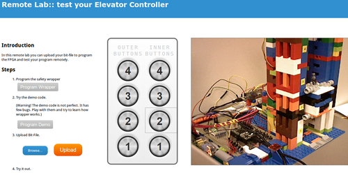
in this project, a remote lab was designed for students (see Fig. 10) to access the controlling hardware from any remote place inside the department INTERA network. The server is running on a raspberry pi and students can see a view of the working lift using an internet camera. A working sample of the controller is provided to the students as a demo in order to get them accustomed to the functionality of the Lift. you can access this lab from this link: cherry.pld.ttu.ee
Web Server
Apache is used for web server, which runs on a Raspberry Pi. Web server's task is to provide the video stream of the elevator via an internet webcam along with virtual buttons for controling the board. In the remote lab page, students can test the lift with a bit file provided to them or they can upload their own bit fils. A Username and password pair has been added for restrictions on access to reduce any inconvinience. Raspberry Pi GPIO's have been used for emulating push button behaviour. All the Server files can be found in here: server files.
When user clicks on buttons on the web page, cgi scripts are called out. Therefore web server has to have cgi-bin enabled and scripts have to have rights to execute. To control the elevator through GPIO, 3rd party application was compiled for this purpose and bash scripts simply call out the program with the corresponding arguments. The physical GPIO connections were wired so, that sending out signal gpio write 2 1 for example, would move the elevator to second floor. More about using GPIO on linux in here.
Note1: a schematic of all the connections for GPIO is needed here.
Lab Reports
Students are required to submit a report in the beginning before starting their designs to describe the process of what they are planning to do and one at the end of the lab along with their codes. A lab report template has been provided for students (You can find it here: File:lab6_template.pdf) and all the reports should be submitted in the same format.
Plans for future improvements
The following improvements are on our todo list:
- queueing system for login in remote lab
- checking the bitfile for malicious codes
- making a 3D model for printing
- providing access for students outside ATI interanet
- PCB design for control board
- adding a micro-controller based control board
- checking if the motor is turned of with switching clock off: this will cause motor to get locked and warm up
- monitoring all the sensors in monitoring system
- adding LEDs to each floor which indicate arival to that floor
