Difference between revisions of "CDS LAB1/en"
From ATI public wiki
((by SublimeText.Mediawiker)) |
((by SublimeText.Mediawiker)) |
||
| Line 45: | Line 45: | ||
: Another window will appear with couple of choices. Choose '''Attach to an existing technology library''' and press '''OK''' | : Another window will appear with couple of choices. Choose '''Attach to an existing technology library''' and press '''OK''' | ||
| − | :[[File:Cds lab1 8.png| | + | :[[File:Cds lab1 8.png|new library technology]] |
| + | |||
| + | : In the next window choose '''TECH_C18A6''' and press '''OK''' | ||
| + | :[[File:Cds lab1 9.png|new library technology]] | ||
| + | |||
| + | ==Creating new circuit into our library== | ||
| + | : Choose the newly created library '''labor_1''' in the '''Library Manager''' window. In the menu choose '''File->New->Cell View''' | ||
| + | :[[File:Cds lab1 10.png|creating new cell]] | ||
| + | |||
| + | |||
| + | |||
| + | : In the window opened fill the field '''Cell''' by giving your new circuit a name, e.g. '''half_adder'''. On the images below ''poolsummaator'' is used as the name. | ||
| + | :[[File:Cds lab1 11.png|creating new cell]] | ||
| + | : Choose '''Applications->Schematics XL''' and select checkbox '''Always use this application for this type of file''' and press '''OK'''. As a result the schematic editor window will open. | ||
| + | |||
| + | |||
| + | == Editing the half-adder schematic == | ||
| + | |||
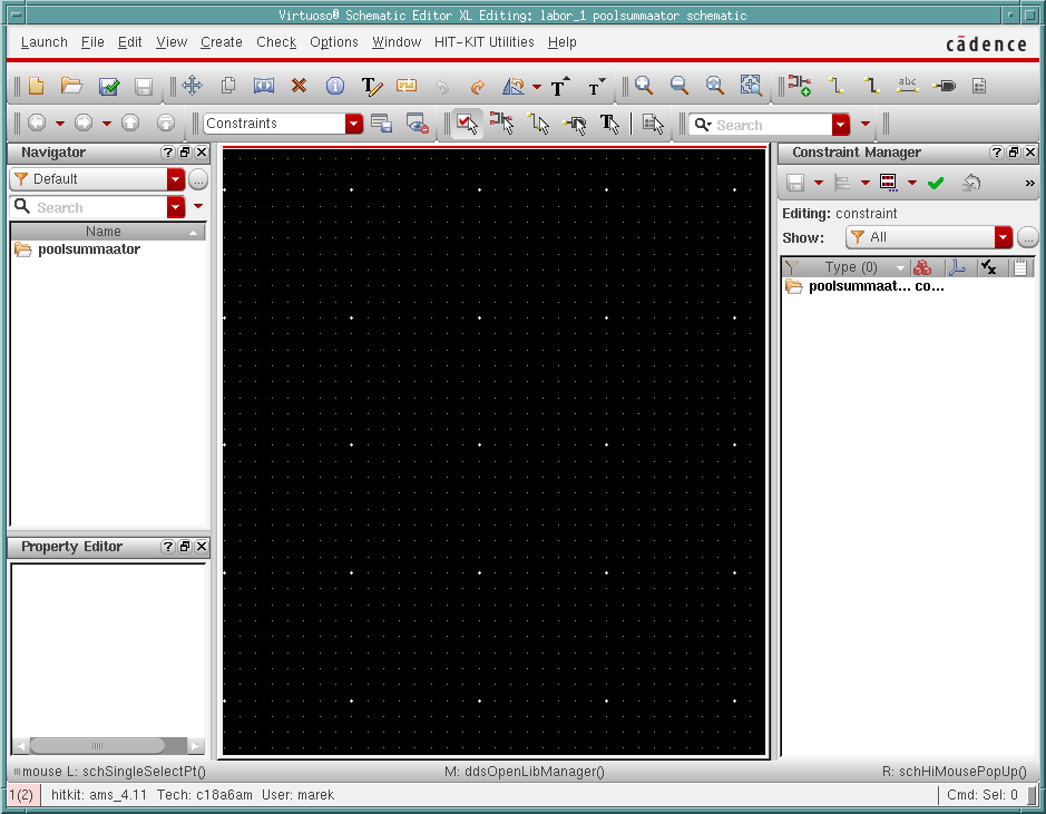
| + | : As a result of the previous actions we should have a schematic editor window open. | ||
| + | :[[File:Cds lab1 12.png|Cadence schematic editor]] | ||
| + | |||
| + | |||
| + | : overview of some of the schematic shortcuts | ||
| + | :* ''''i'''' - '''''instance''''' , adding new instance of a cell to the schematic | ||
| + | :* ''''w'''' - '''''wire''''' , adding wire to the schematic for connecting elements | ||
| + | :* ''''l'''' - '''''label''''' , inserting a label on a connection | ||
| + | :* ''''p'''' - '''''pin''''' , creating a new input/output pin | ||
| + | :* ''''f'''' - '''''fit to view''''' , changes to zoom to fit the whole schematic to the view | ||
| + | :* ''''u'''' - '''''undo''''' , undo the last action | ||
| + | :* ''''X'''' - '''''Check and Save'''' , checks the schematic and saves it | ||
Revision as of 17:49, 9 June 2016
The objective of the tutorial is to design a digital circuit and simulate it using Cadence
Contents
Setting up the work environment
All the actions in this and the followin paragprah will be happening in terminal
- create a new directory lab1
- move to the new directory
- insert 'cad' and from the menu choose '1' (initializes environmental variables for Cadence)
- insert setenv EDITOR SciTE for making SciTE as the default text editor

Starting Cadence
- According to Cadence 2016 EDA ver.
- If it is the first time launching Cadence, then using terminal:
-
ams_cds -64 -tech c18a6 -add CORELIB -add IOLIB_6AM -add GATES_ANA
- here we choose AMS 0.18μm with 6 metal layers as the technology and add three gate libraries
- For the subsequent launches of Cadence use the command:
-
ams_cds

- The actions from this point on will be executed using the Graphical User Interface of Cadence
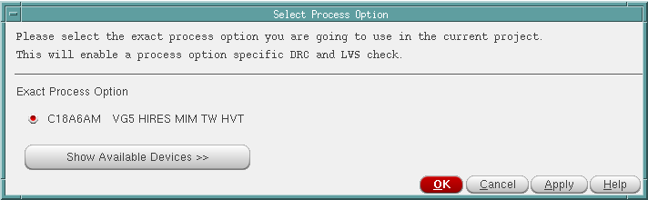
- Several windows will open. On a dialog window asking about designkit simply press OK.

- Cadence main window will be also opening, which is located by default near the left bottom corner.
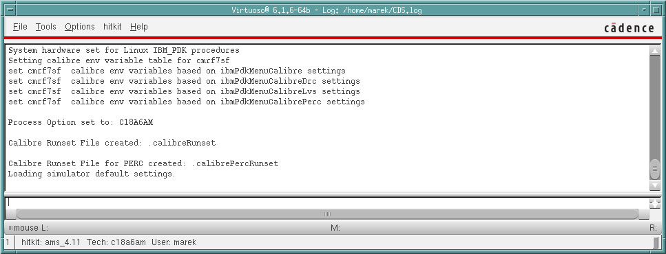
- Cadence will log messages in this window, including error messages.

- Also Cadence Library Manager window will open
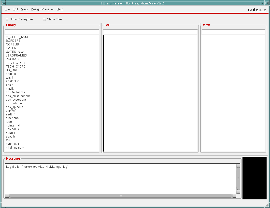
- It is recommended to check the checkbox Show Categories

Creating a new library
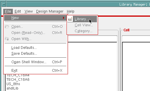
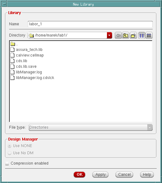
- In the Library Manager window choose from menu File->New->Library

- A new window will open, where a name can be inserted. In here labor_1 will be used. After inserting the name, press OK

- Another window will appear with couple of choices. Choose Attach to an existing technology library and press OK
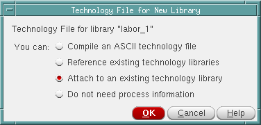

- In the next window choose TECH_C18A6 and press OK


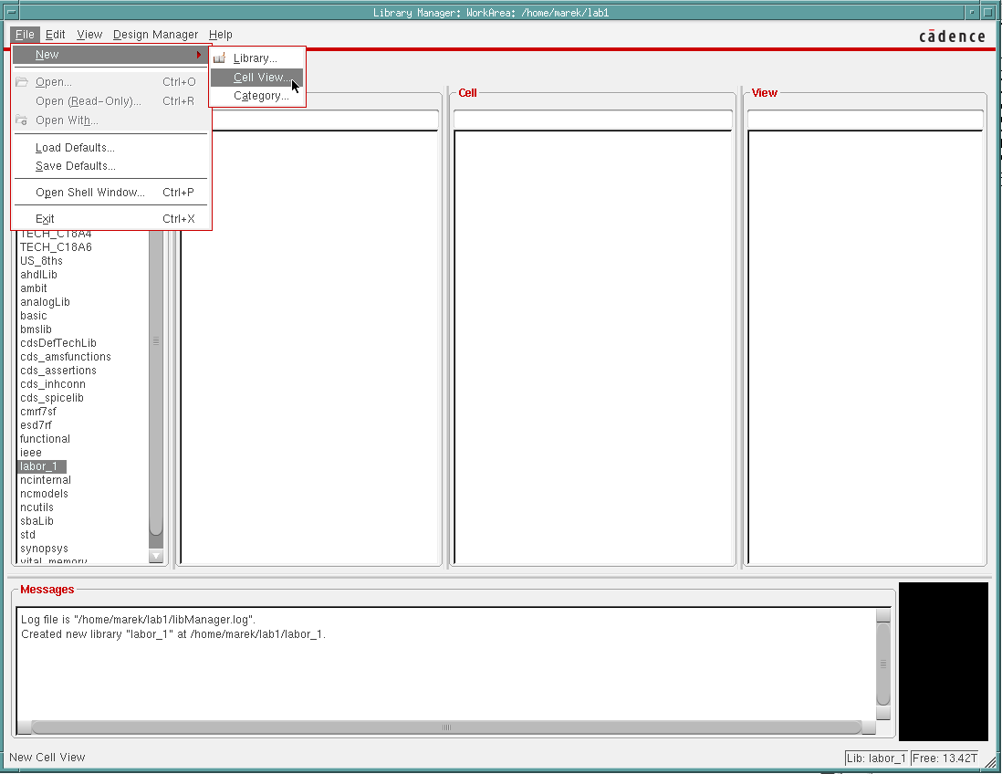
Creating new circuit into our library
- Choose the newly created library labor_1 in the Library Manager window. In the menu choose File->New->Cell View

- In the window opened fill the field Cell by giving your new circuit a name, e.g. half_adder. On the images below poolsummaator is used as the name.
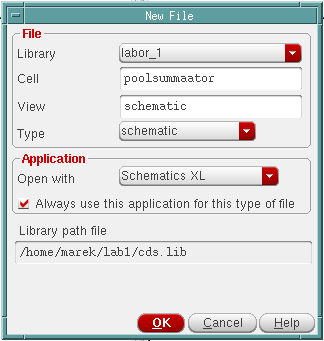
- Choose Applications->Schematics XL and select checkbox Always use this application for this type of file and press OK. As a result the schematic editor window will open.

Editing the half-adder schematic
- As a result of the previous actions we should have a schematic editor window open.

- overview of some of the schematic shortcuts
- 'i' - instance , adding new instance of a cell to the schematic
- 'w' - wire , adding wire to the schematic for connecting elements
- 'l' - label , inserting a label on a connection
- 'p' - pin , creating a new input/output pin
- 'f' - fit to view , changes to zoom to fit the whole schematic to the view
- 'u' - undo , undo the last action
- 'X' - Check and Save' , checks the schematic and saves it