Matriklinumber: 999999-le vastava funktsioonide süsteemi tõeväärtus-tabel oleks järgmine:
0000 1-00
0001 01-0
0010 11-1
0011 0-01
0100 1110
0101 1010
0110 -111
0111 01-0
1000 0011
1001 -10-
1010 -0-1
1011 1001
1100 11-0
1101 0-10
1110 -000
1111 1011
Seda tabelit kirjeldav VHDL-kood oleks järgmine (vt. ka VHDL faili):
library IEEE; use IEEE.std_logic_1164.all;
entity f_system is
  port ( a, b, c, d: in std_logic;
         k, l, m, n: out std_logic );
end entity f_system;

library IEEE; use IEEE.std_logic_1164.all;
architecture tabel of f_system is
begin
  process (a, b, c, d)
    variable in_word, out_word: std_logic_vector (3 downto 0);
  begin
    in_word := a & b & c & d;
    case  in_word  is
      when "0000" => out_word := "1-00";
      when "0001" => out_word := "01-0";
      when "0010" => out_word := "11-1";
      when "0011" => out_word := "0-01";
      when "0100" => out_word := "1110";
      when "0101" => out_word := "1010";
      when "0110" => out_word := "-111";
      when "0111" => out_word := "01-0";
      when "1000" => out_word := "0011";
      when "1001" => out_word := "-10-";
      when "1010" => out_word := "-0-1";
      when "1011" => out_word := "1001";
      when "1100" => out_word := "11-0";
      when "1101" => out_word := "0-10";
      when "1110" => out_word := "-000";
      when "1111" => out_word := "1011";
      when others => out_word := "----";
    end case;
    k <= out_word(3);    l <= out_word(2);
    m <= out_word(1);    n <= out_word(0);
  end process;
end architecture tabel;
9-väärtuseline IEEE loogika (std_logic) on kasutusel
määramatuste p&arast, muidu võiks kasutada lihtsalt
tüüpi bit (vrdl. näidislahenduse
koodiga).
Tespingi VHDL-kood oleks järgmine (vt. ka VHDL faili):
library IEEE; use IEEE.std_logic_1164.all;
entity test is
end entity test;

library IEEE; use IEEE.std_logic_1164.all;
architecture bench of test is
  signal a, b, c, d, k, l, m, n: std_logic;
  component f_system
    port ( a, b, c, d: in std_logic;
           k, l, m, n: out std_logic );
  end component;
begin
  -- Input signaals (after every 10 ns)
  a <= '0' after 0 ns, '1' after 80 ns, '0' after 160 ns;
  b <= '0' after 0 ns, '1' after 40 ns, '0' after 80 ns, '1' after 120 ns;
  c <= '0' after 0 ns, '1' after 20 ns, '0' after 40 ns, '1' after 60 ns,
       '0' after 80 ns, '1' after 100 ns, '0' after 120 ns, '1' after 140 ns;
  d <= '0' after 0 ns, '1' after 10 ns, '0' after 20 ns, '1' after 30 ns,
       '0' after 40 ns, '1' after 50 ns, '0' after 60 ns, '1' after 70 ns,
       '0' after 80 ns, '1' after 90 ns, '0' after 100 ns, '1' after 110 ns,
       '0' after 120 ns, '1' after 130 ns, '0' after 140 ns, '1' after 150 ns;

  -- System of Boolean functions
  U1: f_system port map (a, b, c, d, k, l, m, n);
end architecture bench;
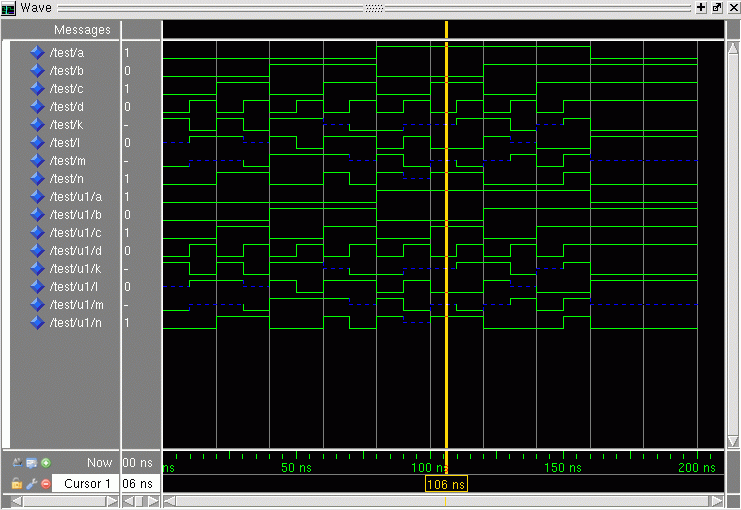
Kõige lihtsam ModelSim'i kasutamise juhend oleks alljärgnev
(keerukam juhend on
siin):
käsk "cad" abil valida Mentor Graphics,
käsk "vsim &" paneb simulaatori tööle.
Simulaatori töötades "File->New->Library..." abil luua teek
"work",
"Compile->Compile..." abil kompileerida nii funktsioonide süsteem kui
ka testpink.
"Simulate->Start Simulation..." alt eemaldada kõigepealt "Enable
optimization" ja seejärel valida "work" seest "test".
Aktiveerige alam-aken "Objects" ja "Add->To Wave->Signal in Design"
lisab kõik signaalid lainekuju aknasse.
Simulaatori käsureal "run 200 ns" teostab simuleerimise.
Aktiveerige alam-aken "Wave" ja menüüst "Wave->Zoom->Zoom
Full" täidab akna ühtlaselt tulemustega.
Võrrelge tulemusi lähteülesandega.

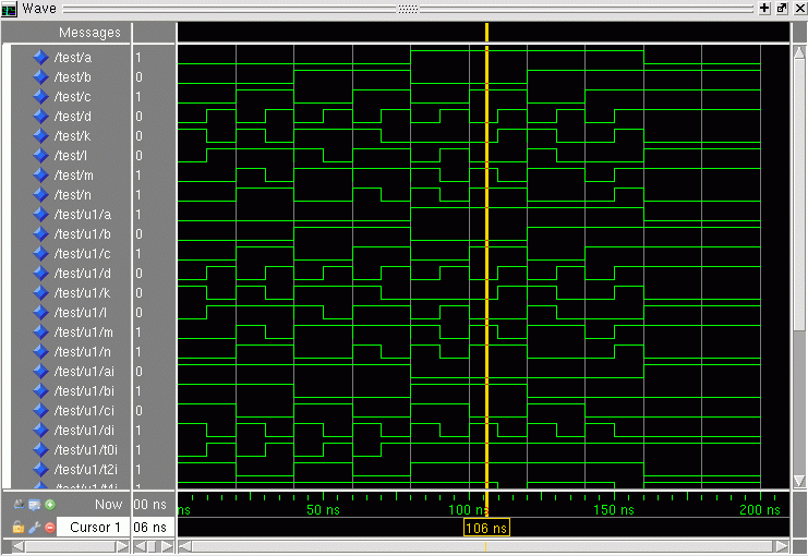
Korrake seda sama (kompileerimine & simuleerimine) loogika-tehete tasemel oleva optimeeritud skeemiga (vt. ka VHDL faili):
library IEEE; use IEEE.std_logic_1164.all;
entity f_system is
  port ( a, b, c, d: in std_logic;
         k, l, m, n: out std_logic );
end entity f_system;

library IEEE; use IEEE.std_logic_1164.all;
architecture opti of f_system is
  signal ai, bi, ci, di: std_logic;
  signal t0i, t2i, t4i, t6x, t6i, t7i, t9i: std_logic;
  signal t51, t52, t53i, t54, t1t8i, t3t6i, t5t6i: std_logic;
begin
  ai <= not (a and a);          bi <= not (b and b);
  ci <= not (c and c);          di <= not (d and d);

  t0i <= a or d;                t2i <= not (ai and c);
  t4i <= not (a and c and d);   t6x <= not (c or d);
  t6i <= not (b and t6x);       t7i <= not (b and d);
  t9i <= not (bi and c);

  t51 <= not (a and d);         t52 <= b xor d;
  t53i <= not (a and bi);       t54 <= not (t2i and t53i);

  t1t8i <= not (di and t54);    t3t6i <= not (t52 and ci);
  t5t6i <= not (t51 and b and ci);

  k <= not (t0i and t4i and t5t6i);
  l <= not (t2i and t3t6i);
  m <= not (t1t8i and t6i and t7i);
  n <= not (t1t8i and t4i and t9i);
end architecture opti;
Võrrelge tulemusi lähteülesandega.

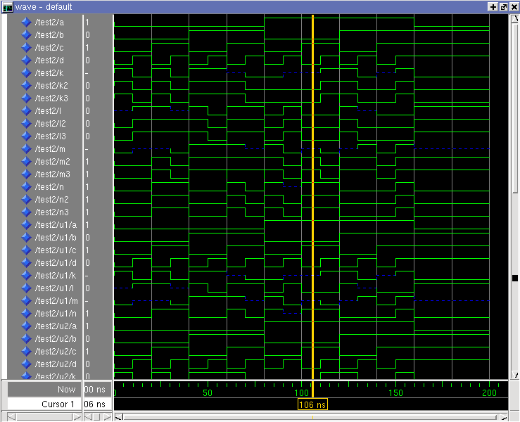
Kõige mugavam oleks, kui saaks omavahel võrrelda 2-3 eri etappi sama simulatsiooni käigus. Heaks näiteks on alljärgnev testpink, mis lubav korraga simuleerida kolme disaini (algne tabel, espresso tulemus ja optimeeritud skeem). Sama olemi kolme erineva arhitektuuri kasutamine on testpingis kirjas for-klauslite abil (vt. arhitektuuri deklaratiivse osa lõppu). Sama kood on ka failist leitav:
library IEEE; use IEEE.std_logic_1164.all;
entity test2 is
end entity test2;

library IEEE; use IEEE.std_logic_1164.all;
architecture bench of test2 is
  signal a, b, c, d, k, l, m, n: std_logic;
  signal k2, k3, l2, l3, m2, m3, n2, n3: std_logic;
  component f_system
    port ( a, b, c, d: in std_logic;
           k, l, m, n: out std_logic );
  end component;
  for U1: f_system use entity work.f_system(tabel);
  for U2: f_system use entity work.f_system(espresso);
  for U3: f_system use entity work.f_system(opti);
begin
  -- Input signaals (after every 10 ns)
  a <= '0' after 0 ns, '1' after 80 ns, '0' after 160 ns;
  b <= '0' after 0 ns, '1' after 40 ns, '0' after 80 ns, '1' after 120 ns;
  c <= '0' after 0 ns, '1' after 20 ns, '0' after 40 ns, '1' after 60 ns,
       '0' after 80 ns, '1' after 100 ns, '0' after 120 ns, '1' after 140 ns;
  d <= '0' after 0 ns, '1' after 10 ns, '0' after 20 ns, '1' after 30 ns,
       '0' after 40 ns, '1' after 50 ns, '0' after 60 ns, '1' after 70 ns,
       '0' after 80 ns, '1' after 90 ns, '0' after 100 ns, '1' after 110 ns,
       '0' after 120 ns, '1' after 130 ns, '0' after 140 ns, '1' after 150 ns;

  -- System of Boolean functions
  U1: f_system port map (a, b, c, d, k, l, m, n);
  U2: f_system port map (a, b, c, d, k2, l2, m2, n2);
  U3: f_system port map (a, b, c, d, k3, l3, m3, n3);
end architecture bench;
Võrrelge tulemusi eelnevate simulatsioonidega. Signaalid k2, k3, l2, l3, m2, m3, n2 ja n3 on käsitsi ümberjärjestatud. Selle tulemusena on hästi näha, kuidas väärtused eri mudelitel kokku langevad...

Korrake kõike seda sama ka omaenda kodutöö ülesandega. Kõigepealt tõeväärtus-tabeliga, siis vahepealsete tulemustega ja kõige lõpuks lõpliku skeemiga...
Viimati muudetud 15.09.2015.