FIR Filter
Task Description:
Finite Impulse Response (FIR) filter is one of the most widespread numerical filters. It is used practically everywhere in numerical signal processing including mobile phones. The name of the filter comes from the fact, that single pulse passes the filter within a finite amount of time. This time depends on the filter order: it's the number of used coefficients. Testing of the filter is based on the following feature - give a single pulse to the input and in finite amount of time you must get all the filter coefficient values in the output. You must design FIR filter with the order of nine, this means that design function is:
data_out= ∑ ci * data_ini-1, where i=1, 2, ..., 9 and data_in-i is delay for i cycles of input data_in.
In this lab everybody gets their own task, however a lot of basic solutions coincide. Therefore teamwork is welcome. The difference of the tasks is in the values of coefficients, which you can find according to your matriculation number remainder of division with 2, 3, 4, 5 and 7 gives you one of the coefficients according to the table below. The filter is symmetrical (c1=c9), thus order of indexes (incremental or decremental) is not important.
| Divisor -> | 3 | 4 | 7 | 5 | 2 |
|---|---|---|---|---|---|
| Remainder | c1, c9 | c2, c8 | c3, c7 | c4, c6 | c5 |
| 0 | 0,125 | 0,25 | -0,75 | 1,25 | 1,0 |
| 1 | -0,125 | -0,25 | 0,75 | -1,25 | 1,25 |
| 2 | 0,25 | 0,5 | -0,625 | 0,75 | |
| 3 | -0,5 | 0,625 | -0,75 | ||
| 4 | 0,875 | 0,875 | |||
| 5 | -0,875 | ||||
| 6 | 1,125 |
Initial data
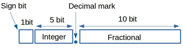
- You will use 16 bit, fixed-point data: 1 bit for sign bit, 5 bits to the left side of the point (integer part), 10 bits to the right side of the point(fractional part). See the image below:
- Filter's order is 9 (or we can say it has 9 taps), coefficients could be found from the table above
- Define entity as following:
library IEEE;
use IEEE.std_logic_1164.all;
use IEEE.std_logic_arith.all;
entity fir_filter is
port ( data_in: in signed (15 downto 0); --input samples
data_out: out signed (15 downto 0); --Filter output
sample : in bit; --start reading the sample(reading enable)
clk: in bit );
end fir_filter;
- All calculations must be performed in 4 cycles (signal clk)
- Input and output of the data occur only if signal sample is true (not faster than every four cycle)
Hints
- To output real number in VHDL: debug_out<=real(conv_integer(data_out))/1024.0;
- you can replace multiplication with shift and add operation. for example: 5 * a = 4 * a + a = (a << 2) + a;
- In division the round-up is not important.
- To test the filter's behavior a pulse with value 1 (which is equivalent to 1.0 or in our data format presented as 040016) is used since the filter will output the coefficients in order (see wave diagram in Fig. 1).
- 16-bit adder's approximate parameters:
Name Area Delay Small-slow 124 19 ns Quick-big 570 5,9 ns - 16-bit multiplexer's approximate parameters:
Name Area Delay Small-slow 2080 36 ns Quick-big 3860 21 ns
Filter example
Try to understand the behavior of the filter by using the following applet.
There are some sample solutions of FIR on the RTL level. You can use them as a codebase for your own.
Behavioral FIR filter simulation example

Figure 1. Sample of a simulation result of the behavioral design.
Tasks
- Create a behavioral module with your coefficients. You can take the code FIR_beh.vhd as basis for your module. This time you must write your own testbench. Simulate and make sure that module works correctly (Figure 1).
- Choose architecture (use the simplest computational units as possible), transform operations (if it is needed), schedule operations among cycles, create necessary registers, bind operations to resources (your computational units). According to the results of scheduling and binding write corresponding RTL code. The example of the RTL code can be taken from RTL samples. Simulate your RTL code to check to correctness of the behavior.
- For Debugging, check here.
- Synthesize your FIR filter using Synopsis. Take a clock period of 20 ns. If it is necessary change the code in order to get the smallest possible area (must be less than 3500). See the Guide to Synopsis here.
- Write a report which contains:
- Behavioral, RTL and testbench code.
- Simulation results: behavioral and RTL.
- Made transformations: transformations of operations, scheduling and binding of operations.
- Synthesis results (area, delay, number of registers) and analysis. Especially when delay 20 ns is not achieved.
Questions
- Why and where is FIR filters used?
- What is the main concept of FIR filters (how do they function)?
Related Readins