Arithmetic Logic Unit (ALU)
Task description
An Arithmatic Logic Unit (ALU) is a combinational logic circuit that can perform different arithmetic and bitwise logical operations on integer binary numbers. ALU is the fundamental building block of many computing circuits including Central Processing Units (CPUs).
An ALU usually takes two inputs, called operands, and a code, called OPCODE, which specifies the operation to be performed on the operands. ALU also has a result output which is the result of the operation on the operands. In some designs, usually the values (operands) fed to the ALU and/or the result generated from ALU are read from/stored in registers. A general symbolic representation of an ALU is shown in Figure 1.
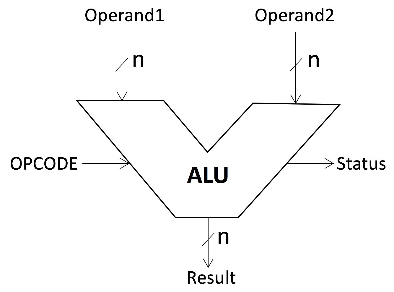
Figure 1. A symbolic representation of an ALU
As it can be seen in Figure 1, an ALU might also have one or more Status signals on the output, which carry supplemental information about the results of the operation, for example, it can be a carry-out/borrow bit, zero bit, negative, overflow and parity. In this tutorial, we intend to design an ALU at high level using behavioral description in SystemC.
Tasks
- Use SystemC to design a 4-bit ALU circuit at the behavioral level having the following functionalities:
- The ALU should take in two 4-bit numbers.
- Add the two numbers.
- Subtract the two numbers.
- Increment the first operand (OP1) by 1.
- Decrement the first operand (OP2) by 1.
- Bit-wise AND the two numbers.
- Bit-wise OR the two numbers.
- Bit-wise NAND the two numbers.
- Bit-wise XOR the two numbers.
- The output of the ALU consists of one 4-bit result (RESULT), a carry/borrow bit (CARRY) and a zero bit (ZERO).
- For this purpose, the base code of the ALU is provided in ALU.h and ALU.cpp. Study the codes and try to match the required functionalities mentioned above with the operations that the ALU can do.
- The ALU mentioned here can do 8 different operations. Try to figure out how many bits you would need for the OPCODE in order to design the ALU and address 8 operations. Also, based on the required operations, try to find out which of the Status outputs are required (carry-out/borrow bit, zero bit, negative, overflow and parity).
- For the OPCODEs, create a table as shown in Table 1, and fill the values of OPCODEs based on the operations mentioned earlier.
Table 1. OPCODE table of the ALU along with their operations
OPCODE Operation Add Subtract Increment OP1 Decrement OP1 Bit-wise AND Bit-wise OR Bit-wise NAND Bit-wise XOR - Create the corresponding test-bench and simulation files to verify your design. Create a VCD file of the signals and visualize them using GTKWave.
Related Readings