CDS V
Purpose of this tutorial is how to import Verilog netlist into Cadence Virtuoso
Contents
Setting up the environment
following commands are all in commandline
- move to your design folder noc_synth
- I created a separate folder for virtuoso, to keep folder structure more clear.
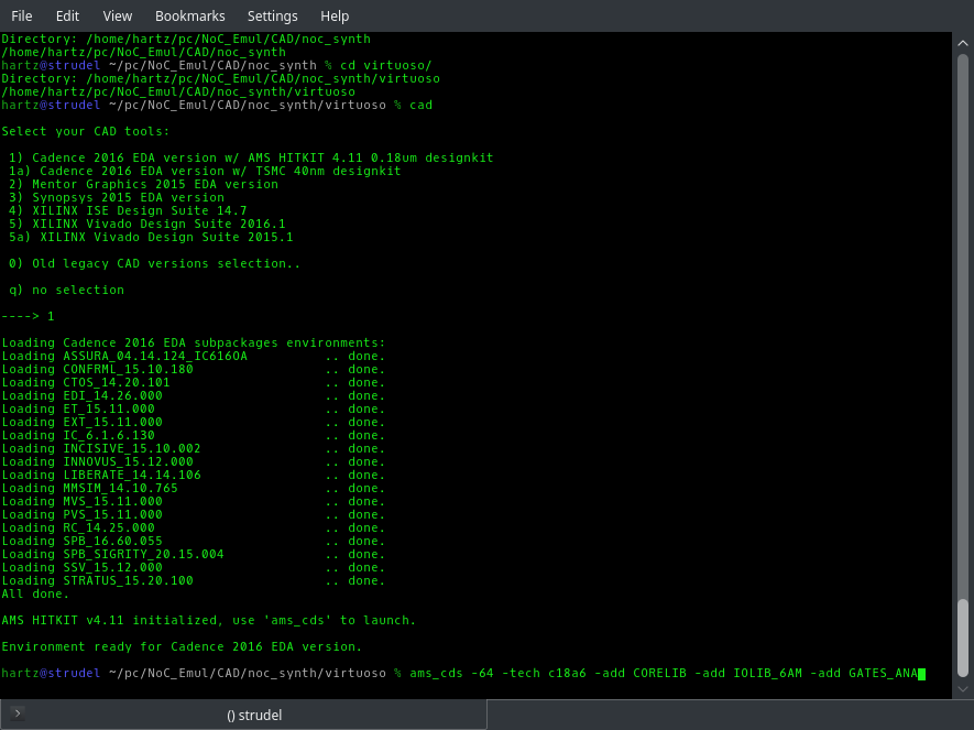
- using command 'cad', choose option '1' to initialize environment variables for Cadence tools.
Bringing up Virtuoso
- If this is the first time using Virtuoso for this design, run following command to invoke Virtuoso. This will set up Virtuoso to use AMS 0.18μm technology with 6 metal layers, including some element libraries.
-
ams_cds -64 -tech c18a6 -add CORELIB -add IOLIB_6AM -add GATES_ANA
- If you are sure that you have already invoked the previous command, you can just bring up Virtuoso with command
-
ams_cds
When running Virtuoso first time, with that longer command, you will be asked some additional information about the design kit.
Luckily there will be only one option and you can just click OK.
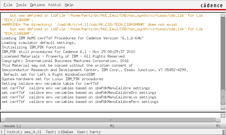
After that Virtuoso's main window will open, which should appear in the left bottom corner of your screen.
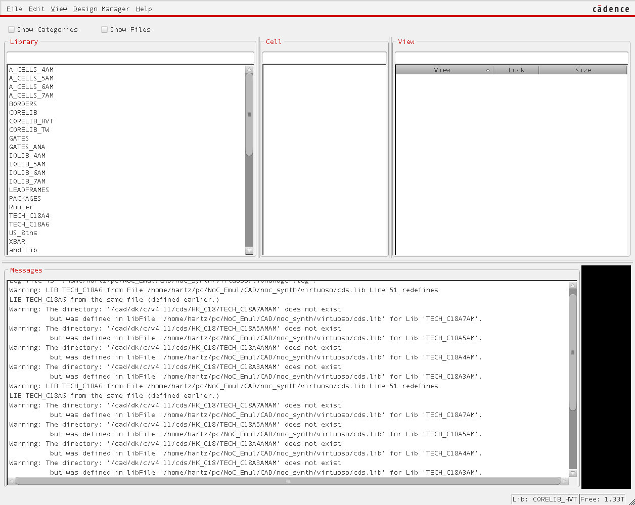
All messages, including Warnings and Errors will be displayed there. Also second window, Library Manager, will open.
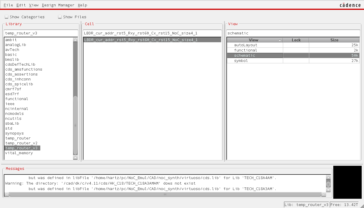
Later on your imported design will be also listed there.
Importing the design
NB!
Before starting to import your Verilog netlist file, run it through script that remaps wire connections based on the assignments and finally removes them from the Verilog netlist file. It is needed to remove the assignments because they are, for some wired reason, represented in Cadence as cds_thru gates. These are essentially INOUT ports.
script can be invoked on command-line
-
./rm_assign.sh
-
Script usage is following:
 Script for re-mapping directly given assignements in verilog netlist
 Give input verilog netlist filename .
     -I <netlist_in.v>
 Give output verilog netlist filename.
     -O <netlist_out.v>
 Example:
  :/~> ./rm_assign.sh -I <netlist_in.v> -O <netlist_out.v>
Script can be downloaded here.
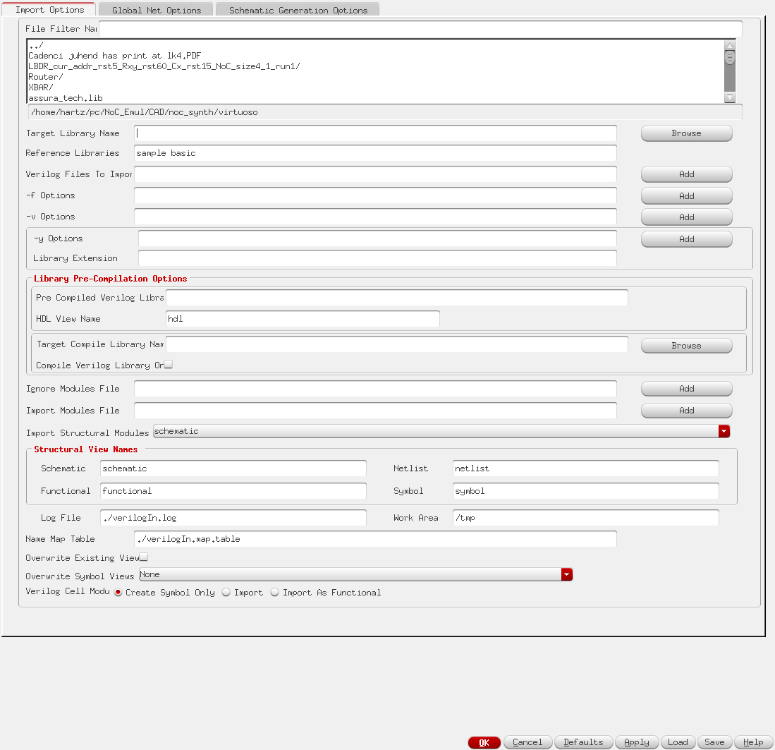
To import a design into Virtuoso, under 'File' menu in the main window, find 'import' and click 'Verilog' This should bring up a window called 'Verilog In'
Importing Verilog needs a lot of configuration, so these step-by-step explanations will follow:
Set target library Name
This can be done in two ways
- If importing a new design you can give what ever name here, that is not listed in the Library Manager window under 'Library' pane.
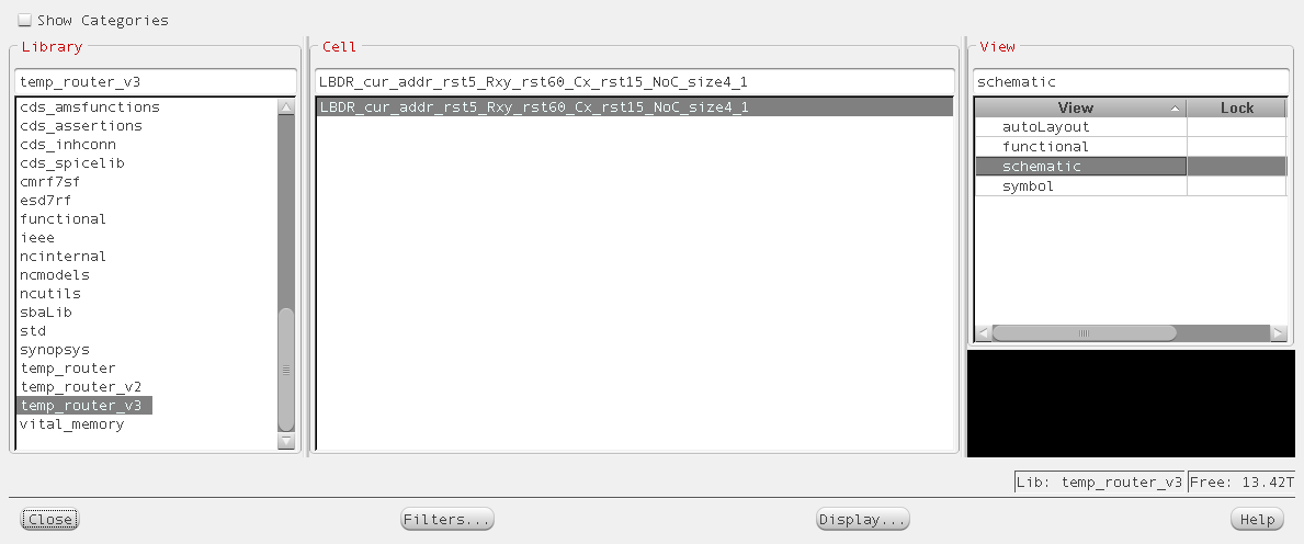
- If importing a new or modified component (cell in another word) of previously imported design click Browse. It will bring up similar windows to Library Manager, where you can find your previous design. After selecting your design library, click OK and the library will appear in the Verilog In window.
The filled target library field should look similar to this.
Add Reference Libraries
In this field ADD libraries called CORELIB and BORDERS CORELIB will include all AMS technology gates and elements. Borders will include border graphics in schematic view.
Add Verilog file(s) to import
- First step is to find the file in 'Folder view', which is located top side of the Verilog In window. By default it will display the folder from where you invoked the Virtuoso. It is possible to move to parent folder by double-clicking '../' in the first row or moving into some other folder by doing the same thing on a folder name.
- When in the folder where the Verilog source file is, select it.
- To add the file, click on the Verilog Files To Import line Add button.
Finalizing Import Options
- Find the option Import Structural Models and change it to 'schematic and functional'.
- If you are planning to overwrite your previous component/cell change the Overwrite Symbol Views to 'ALL'.
- Also change the Verilog Cell Module to 'Import'.
Global Net Options
As a next step it is needed to change the Power and Ground names to lower case. This can be done in the 'Global Nets Options' tab which can be selected top of the Verilog In window.
Schematic Generation Options
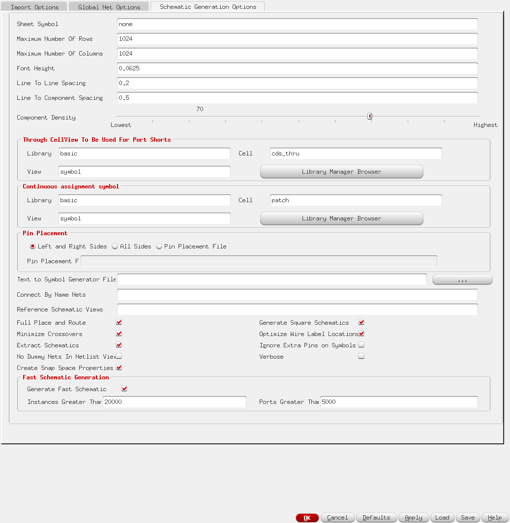
Select the third tab, 'Schematic Generation Options', on the Verilog Inwindow.
- Drag Component Density slider between values of 50 and 70. This helps the Cadence software to more easily and also faster generate the initial schematic, while keeping it reasonably small.
- Tick check boxes of 'Minimize Crossovers' and 'Optimize Wire Label Locations'.
After these steps when OK is clicked, Virtuoso should import your Verilog Netlist file and generate a schematic out of it. Imported design can be seen in the Library Manager window, when selecting your Library and then imported cell/component.
