FPGA Controller prototype
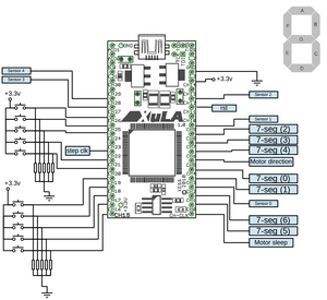
In the first verion of FPGA control board, a Xula FPGA (xs3s200a-4vq100) board has been used (XULA board reference manual). Pin configuration of this board has been shown in Fig. 1.
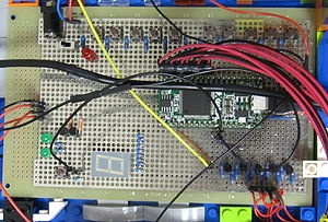
The first prototype control board provides the following functionalities (see Fig.2):
- Seven segment display
- Infra Red (IR) sensors at each floor note: we need schematic of sensor circuit here
- Inner and outer cabin push buttons
- Motor state indicator LEDs note: which LED shows what?
- Software reset button
- Hardware break at top floor
- Power switch for motor
Contents
System Components, Signal Names and Description
Top level design entity that students are required to design's interface has been described in the table below:
| Name | Port | type |
|---|---|---|
| clk | in | STD_LOGIC |
| sensors | in | STD_LOGIC_VECTOR (4 DOWNTO 0) |
| calls | in | STD_LOGIC_VECTOR (4 DOWNTO 0) |
| menu | in | STD_LOGIC_VECTOR (4 DOWNTO 0) |
| rst | in | STD_LOGIC |
| motor | out | STD_LOGIC_VECTOR (1 DOWNTO 0) |
| sleep | out | STD_LOGIC |
| Seven_Segment | out | STD_LOGIC_VECTOR (6 DOWNTO 0) |
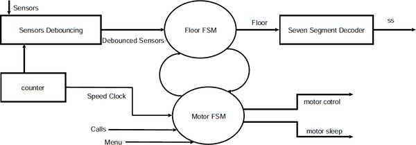
The control system itself has different components that have been shown in Fig. 3. In this figure:
- Counter is a 24 bit counter in the design.
- Sensors should be designed according to the following functionality :
- Sensors are prone to bouncing because of vibrations in the lift which might not be visible to the naked eye but is visible to the sensors. Hence the sensors need to be de-bounced by a three bit shift register with 19th bit of counter slowing the de-bouncing circuit.
- The lift has five ray cut Infra-Red (IR) sensors.
- When ever a sensors ray is cut by the lift it sends a signal '1' to the FPGA. Otherwise the sensor sends a '0'
- Each sensor is placed between floors and there can be blind spots between each sensor. When the lift is in a blind spot all sensors send "00000" to the FPGA. This is the time when the lift is moving between two sensors. At this point sensors can also recieve value from two sensors as well. (e.g. on the second floor sensors can either have a value "00000" or "00110".) It is recommended that both cases should be handled by the designer. (hint: rather then looking for sensor ="00100" look for sensor(2)= "1".)
- Motor should be controlled in the following manner by motor FSM
- Motor(0) controls the direction of the motor. Where '1' is DOWN '0' is up
- Motor(1) generates a clock signal which controls the speed of the motor. The speed is specified by a clk like signal by changing its frequency. The recommended speed of Motor can be given by sending 10th bit of the counter.
- A sleep signal turns off the motor. In idle state the motor should be kept turned off. where '1' is ON and '0' is OFF
- Motor FSM should also shares its Status with Floor FSM ( i.e. idle, going up, going down, blinking Seven segment)
- Seven segments should work as follows
- Seven segment decoder decodes the current floor into seven segment output.
- while designing 7seg decoder you should keep in mind that unlike seven segments on Nexys FPGAs you do not need to specify the anode.
- Each segment is turned on by logic value 1. Seven segment should also be able to blink 5 times after it reaches a floor.
- Unlike nexys 2/3 board's seven segment the pin orientation is opposite. (i-e. seven segment <= "abcdefg";)
- When the elevator reach a particular floor then it should stop and blink the floor number for 5 seconds.
- The Floor FSM should work in the following manner.
- FSM floor calculates the current floor based on the sensor and the Motor FSM status (direction sleep).
- The sensors have blind spots Hence the floor FSM should remember its own floor while passing through the blind spot
The User Constraints File (UCF) File
The following code is the UCF file for XULA board:
 NET "clk" LOC = P43;
 NET "m0" LOC = P56; # Direction
 NET "m1" LOC = P13; # step clock
 NET "sleep" LOC = P44; # sleep to disable the motor

 NET  "rst" LOC = P83;

 NET "Seven_Segment(6)" LOC = P37;
 NET "Seven_Segment(5)" LOC = P36;
 NET "Seven_Segment(4)" LOC = P57;
 NET "Seven_Segment(3)" LOC = P61;
 NET "Seven_Segment(2)" LOC = P62;
 NET "Seven_Segment(1)" LOC = P50;
 NET "Seven_Segment(0)" LOC = P52;

 NET "calls(0)" LOC = P21;
 NET "calls(1)" LOC = P32;
 NET "calls(2)" LOC = P33;
 NET "calls(3)" LOC = P34;
 NET "calls(4)" LOC = P35;

 NET "menu(0)" LOC = P3;
 NET "menu(1)" LOC = P4;
 NET "menu(2)" LOC = P7;
 NET "menu(3)" LOC = P19;
 NET "menu(4)" LOC = P20;

 NET "sensors_in(0)" LOC = P39;
 NET "sensors_in(1)" LOC = P68;
 NET "sensors_in(2)" LOC = P82;
 NET "sensors_in(3)" LOC = P97;
 NET "sensors_in(4)" LOC = P94;
Safty Monitoring Mechanism
Since this model is designed to be controlled remotely, it should be able to maintain its functionality even if it is programmed with a faulty design. For this reason we need some monitoring system to guarantee the functionality.
hardware break
A physical switch has been installed on the top floor to prevent faulty designs to go through the roof. Basically this switch is placed for worst case scenarios where there is no other way to prevent the catastrophe and where it cuts the motor power and stops the motor.
behaviour monitor
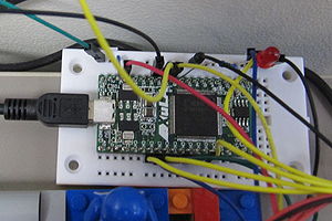
Since reaching hardware break will require human intervention and it would not always possible (in times that an operator is not present etc.), a behaviour monitor system (see Fig. 4) has been added to the lift. Motor control signals goes through the monitoring system which has another Xula FPGA (xs3s200a-4vq100) board. If monitoring system detects a suspicious behaviour it takes over the control and brings the lift to the initial position and sends a reset signal to the control board. At the moment the following cases are covered:
- Going up at the top floor
- Unwinding the thread at first floor
Here you can download the programming bitfile for monitoring FPGA: File:wrapper.bit. The following is the UCF file for the wrapper Xula FPGA:
NET "clk" LOC = P43;
NET "fpga_direction" LOC = P97;
NET "fpga_sleep" LOC = P4;
NET "fpga_clk" LOC = P12;
NET "top_sensor" LOC = P68;
NET "bottom_sensor" LOC = P72;
NET "reset_to_controller" LOC = P83;
NET "motor_direction" LOC = P94;
NET "motor_sleep" LOC = P3;
NET "motor_clk" LOC = P20;
NET "top_sensor_out" LOC = P62;


