FIR Filter in SystemC
Lab Description:
As mentioned in Lab 1, Finite Impulse Response (FIR) filter is one of the most widespread numerical filters. The purpose of this lab is to get familiar with SystemC language for describing hardware, i.e. we want to re-design the FIR filter using SystemC. To this end, first a sample design of a 4 to 1 multiplexer with a register on output is provided for you for getting acquainted with the concept of describing combinational/sequential modules in SystemC and simulating them, while having the knowledge of VHDL as background. Also, in order to verify the correctness of the design, the testbench for the multiplexer with register in SystemC is provided, which can be visualized using either ModelSim or GTKWave. During the second part of this lab the goal is to map the knowledge gained from VHDL to SystemC for modeling hardware. To this end, the final FIR filter that you have designed in VHDL should be mapped to SystemC, along with writing a testbench for it to verify the design. For this part of lab, also some different implementations of FIR filters in SystemC are provided which can be used as templates.
Prerequisites
- It is recommended to have C++ programming knowledge as it can make the process of writing in SystemC language easier.
- In order to install SystemC library and GTKWave on your system, you can click on Setup Your System on the left column of this page.
- For reading about describing modules in SystemC (somehow similar to entities in VHDL), processes (for describing concurrency), and various data types introduced in SystemC, you can refer to this link. Also, the lecture slides of this course for SystemC language can be accessed here.
- More information regarding translation rules from VHDL to SystemC can also be obtained from this link.
Hints
- The data format is similar to the VHDL FIR filter lab (16 bit, fixed-point data), as shown below:
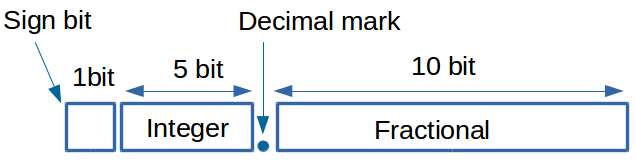
For representing this data format in SystemC, you can use the fixed datatype (sc_fixed) as follows:
sc_fixed <16,6> sample_data; // Specifies sample_data as fixed datatype, 16 bits in total, 6 bits considered for the integer part and the rest (10 bits) for the fraction part.
In order to be able to use the sc_fixed datatype in your code, you can either write the following statement on top of every file in which you use it:
#define SC_INCLUDE_FX
Or, if it does not work, you can include the file sc_fixed.h, using the following path:
#include "/cad/sysC/2.2/include/sysc/datatypes/fx/sc_fixed.h" - A module in SystemC is defined as follows (using the keyword SC_MODULE) :
#include <systemc.h>
SC_MODULE (fir_filter)
{
// Ports
sc_in <sc_fixed <16,6> > data_in;
sc_in <bool> sample , clk;
sc_out <sc_fixed <16,6> > data_out;
};
- Similar to VHDL, in SystemC : 5 * a = 4 * a + a = (a << 2) + a;
- In order to test the behaviour of the FIR filter, a pulse with value 1.0 (equivalent to 0400 in hexadecimal base in our data format) is the best as input (as shown in the wave diagram of Figure 1).
- For generating clock signal when specifying the test-bench, you can do as following:
- When simulating using g++ , you can use the SystemC's default clock notation or generate the clock signal using a separate process in the test-bench (which is also explained in the lecture slides).
- When simulating using ModelSim, you should generate the clock signal using a process (not using SystemC's clock notation).
Generating clock signal using SystemC's clock notation:
sc_clock clk ("clock_name", clock_period , time_unit, duty_cycle, first_edge_time,first_edge_time_unit, first_edge_falling_or_rising)
Example: sc_clock clk ("clk", 5,SC_NS, 0.25, 3,SC_NS, true) // Specifies a clock with period of 5 ns, duty cycle of 0.25, first edge at 3 ns and first edge is rising.
Generating clock signal using a process:
void proc_clk()
{
while (1)
{
clk.write (false);
wait (10,SC_NS);
clk.write (true);
wait (10,SC_NS);
}
}
Compiling and simulating SystemC using ModelSim Simulator
In order to run SystemC in ModelSim you need to make some changes in the original SystemC code. More details are provided in ModelSim's User Manual (page 56).
- To compile systemC files you need to type in the command line:
sccom filename
or
Compile -> Compile Selected (you can’t compile .h files) - Then you need to link the design:
Compile-> SystemC Link
or from command line:
sccom –link - Afterwards, simulate and run as you’ve done using VHDL and Verilog. Don’t forget to change default time units of Resolution in Start Simulation Window.
- 4 to 1 multiplexer code: mux_4_to_1.h and mux_4_to_1.cpp written in SystemC.
- The test-bench for the 4 to 1 Mutiplexer is proposed in: mux_4_to_1MS_tb.cpp.
- 4 to 1 multiplexer with register (synchronous output) code: mux_4_to_1_with_reg.h and mux_4_to_1_with_reg.cpp written in SystemC.
- The test-bench for the 4 to 1 multiplexer with register (synchronous output) is proposed in: mux_4_to_1_with_regMS_tb.cpp.
Please note that the codes contain bug(s) intentionally, try to find out where the problem is before simulation.
Compiling and simulating SystemC using g++ compiler and visualization using GTKWave
In order to work with g++ you need to perform the followings:
- To compile SystemC files you need to type in Terminal window:
g++ -I/cad/sysC/2.2/include -L/cad/sysC/2.2/lib [file name] ... [file name] -lsystemc - The file names should be written in order of the hierarchy in the design, from the design itself to the test bench, separated by space character. To run your program, by default the executable a.out will be created in the same directory, therefore you need to type the following in Terminal window:
./a.out
- It is possible to save signals changes during simulation into trace file, which is in the given examples (for 4 to 1 multiplexer design and 8-bit register design) named “trace”. Signals are said to be dumped into the output files. The extension of the created output file is vcd.
- If you open the trace-it.vcd file in a text editor (such as gedit), you can watch your results in a text form.
- Alternatively, for visualization purposes, you can observe them in GTKWave Electronic Waveform Viewer, by typing in the terminal window:
gtkwave [trace file name]
- 4 to 1 multiplexer code: mux_4_to_1.h and mux_4_to_1.cpp written in SystemC.
- The test-bench for the 4 to 1 Mutiplexer is proposed in: mux_4_to_1_tb.cpp.
- 4 to 1 multiplexer with register (synchronous output) code: mux_4_to_1_with_reg.h and mux_4_to_1_with_reg.cpp written in SystemC.
- The test-bench for the 4 to 1 multiplexer with register (synchronous output) is proposed in: mux_4_to_1_with_reg_tb.cpp.
Please note that the codes contain bug(s) intentionally, try to find out where the problem is before simulation.
FIR Filter examples
Try to understand the behavior of the filter by using the following applet.
There are some sample solutions of FIR on the RTL level in SystemC. You can use them as a codebase for your own. For each design, both a VHDL code and a SystemC code is available.
Behavioral FIR filter simulation example in SystemC
An example of the simulation results of a FIR filter written in behavioural mode in SystemC, visualized using GTKWave is shown in Fig. 1.

Figure 1. Simulation results for behavioural FIR filter in SystemC (using GTKWave)
Tasks
- During this section of this lab, you are going to rewrite the FIR filter that you designed in the VHDL FIR Filter lab and change it from VHDL to SystemC. Therefore, there is no need to redesign the filter from scratch, instead, it is recommended to map the whole design to the SystemC language.
- Create a behavioral module with your coefficients. You can take the code fir_beh.h and fir_beh.cpp a basis for your module, which are based on the coefficients used in the example here. Now you should write a test-bench for the filter and make sure it works correctly. If everything is fine, when you visualize the waves, for instance using GTKWave, you should obtain results similar to Fig. 1. Please note the time instances when the sample input goes active (at which clock edge status (rising or falling)).
- You can use either ModelSim to both compile and visualize the signals, or use g++ to compile and GTKWave to visualize them.
- Similar to the VHDL FIR filter lab, choose architecture (use the simplest computational units as possible), transform operations (if it is needed), schedule operations among cycles, create necessary registers, bind operations to resources (your computational units). According to the results of scheduling and binding write corresponding RTL code, but this time in SystemC. The example of the RTL codes in VHDL can be taken from RTL samples. It is recommended to use the RTL design you have already finalized from the VHDL lab and map it to SystemC code. Simulate your RTL code using the same test-bench you developed for the behavioural design in order to check to correctness of the filter (apply a pulse on input and make sure all the values of the coefficients would be generated on output).
Requirements
-
A report including:
- Behavioral and RTL description of the FIR filter in SystemC along with the written testbench code.
- Simulation results obtained using either GTKWave or ModelSim.
Question
- What is the difference between SC_METHOD and SC_THREAD in SystemC ?
Related Readings